 Ford Kuga Service ManualAuxiliary Climate Control » Auxiliary Climate Control (System Operation and Component Description)
Component Description
Component Description
Electric Booster Heater
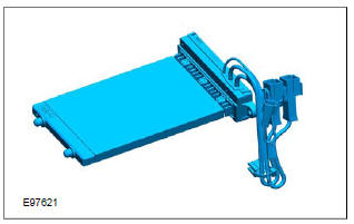
The electric booster heater consists of three individual heating elements, which are incorporated into a single housing. It is controlled by the generic electronic module (GEM), taking into account the following factors:
Detailed illustration of fuel-fired heater
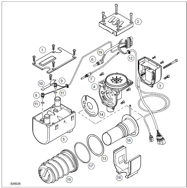
| Item | Description |
| 1 | Cooling sleeve cover |
| 2 | Combustion air blower cover |
| 3 | Fuel fired additional heater module |
| 4 | Combustion Air Blower |
| 5 | Cooling sleeve |
| 6 | Glow plug |
| 7 | Flame sensor |
| 8 | Overheat Sensor |
| 9 | ECT |
| 10 | Compression spring |
| 11 | 'O' Ring |
| 12 | Internal wiring harness - fuel fired additional heater |
| 13 | Gasket |
| 14 | Gasket |
| 15 | Heat exchanger |
| 16 | Combustion chamber |
| 17 | 'O' Ring |
| 18 | Combustion blower motor cover |
| 19 | Glow plug wiring harness |
Flame sensor
If the flame goes out independently during operation of the booster heater, a restart is carried out. If the booster heater does not ignite within 90 seconds of fuel delivery or if the flame goes out within 15 minutes of starting, a lockout will be implemented by the flame sensor.
Lockout can be cancelled by switching the booster heater off then on again, although this may only be repeated at most 2 times.
Overheat Sensor
The overheating sensor enables the fuel-fired booster heater module to determine the coolant temperature, protecting the heater from overheating. The overheating sensor is installed next to the coolant temperature sensor under a cover on the top of the fuel-fired heater.
In the event of overheating (lack of water, poorly ventilated coolant circuit), the fuel supply to the heater is interrupted and a lockout occurs. After the cause of the overheating has been eliminated, the heater can be restarted by switching it off and on again, if the coolant temperature is below 70C.
If the heater overheats ten times in a row, the control unit is locked.
ECT
The fuel-fired booster heater module uses the temperature sensor to determine the coolant temperature, which it then uses to set the starting and stopping time. The coolant temperature sensor is installed next to the overheating sensor under a cover on the top of the fuel-fired heater.
Water pump
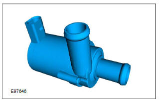
The coolant pump is located on the holder for the fuel-fired heater on the bulkhead in the rear of the engine compartment. The coolant pump is driven by a built-in electric motor and circulates the coolant in the engine cooling system. The delivery rate for the pump is 820l/h at a delivery pressure of 0.1 bar.
Fuel pump
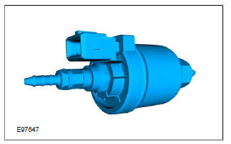
The fuel required for the fuel-fired heater is taken from the fuel system by a fuel pump fitted in the fuel tank and is delivered to the heater via a fuel line.
The fuel pump is an electric piston pump which meters the corresponding fuel volume for the fuel-fired heater according to a cycle set by the fuel-fired heater module.
System Diagram
System Operation
Component Description
Ford Kuga Service Manual
- General Information
- Jacking and Lifting
- Noise, Vibration and Harshness
- Suspension System - General Information
- Climate Control
- Auxiliary Climate Control
- Instrument Cluster and Panel Illumination
- Instrument Cluster
- Horn
- Warning Devices
- Parking Aid
- Charging System - General Information
- Battery, Mounting and Cables
- Generator and Regulator
- Voltage Converter/Inverter
- Information and Entertainment System - General Information
- Information and Entertainment System
- Exterior Lighting
- Interior Lighting
- Daytime Running Lamps (DRL)
- Module Communications Network
- Module Configuration
- Wiring Harnesses
- Anti-Theft - Active
- Anti-Theft - Passive
- Multifunction Electronic Modules
- Front End Body Panels
- Body Closures
- Interior Trim and Ornamentation
- Exterior Trim and Ornamentation
- Rear View Mirrors
- Seating
- Glass, Frames and Mechanisms
- Instrument Panel and Console
- Handles, Locks, Latches and Entry Systems
- Wipers and Washers
- Bumpers
- Safety Belt System
- Supplemental Restraint System
- Body Repairs - General Information
- Body Repairs - Vehicle Specific Information and Tolerance Checks
- Front End Sheet Metal Repairs
- Roof Sheet Metal Repairs
- Side Panel Sheet Metal Repairs
- Rear End Sheet Metal Repairs
- Paint - General Information
- Uni-Body, Subframe and Mounting System
- Suspension System - General Information
- Front Suspension
- Rear Suspension
- Wheels and Tires
- Driveshaft
- Rear Drive Axle/Differential
- Front Drive Halfshafts
- Rear Drive Halfshafts
- Brake System - General Information
- Front Disc Brake
- Rear Disc Brake
- Parking Brake and Actuation
- Hydraulic Brake Actuation
- Power Brake Actuation
- Anti-Lock Control
- Anti-Lock Control - Stability Assist
- Steering System - General Information
- Power Steering
- Steering Linkage
- Steering Column
- Steering Column Switches
- Engine System - General Information
- Engine- 2.5L Duratec (147kW/200PS) - VI5
- Engine Cooling
- Fuel Charging and Controls-2.5L Duratec (147kW/200PS) - VI5
- Fuel Charging and Controls - Turbocharger- 2.5L Duratec (147kW/200PS) - VI5
- Accessory Drive - 2.5L Duratec (147kW/200PS) - VI5
- Starting System- 2.5L Duratec (147kW/200PS) - VI5
- Engine Ignition - 2.5L Duratec (147kW/200PS) - VI5
- Engine Emission Control - 2.5L Duratec (147kW/200PS) - VI5
- Intake Air Distribution and Filtering - 2.5L Duratec (147kW/200PS) - VI5
- Evaporative Emissions
- Electronic Engine Controls
- Automatic Transmission/Transaxle
- Transmission/Transaxle Cooling
- Automatic Transmission/Transaxle External Controls
- Transfer Case
- Exhaust System-
- Fuel System
- Fuel Tank and Lines
- Acceleration Control
- Speed Control
- Climate Control System
- Climate Control
Main Categories

0.0189