 Ford Kuga Service ManualFuel Tank and Lines
Fuel Tank - 2.5L Duratec (147kW/200PS) - VI5
Fuel Tank - 2.5L Duratec (147kW/200PS) - VI5
Removal
WARNING: Avoid flames, sparks or lighted substances.
NOTE: Removal steps in this procedure may contain installation details.
1. Refer to: Battery Disconnect and Connect (414-01 Battery, Mounting and Cables, General Procedures).
4x4
2. Refer to: Driveshaft (205-01 Driveshaft, Removal and Installation).
All vehicles
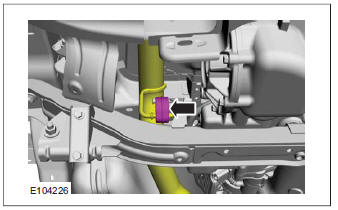
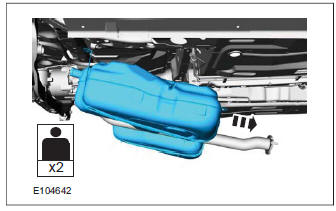
3. Torque: 48 Nm

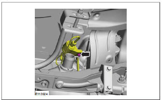
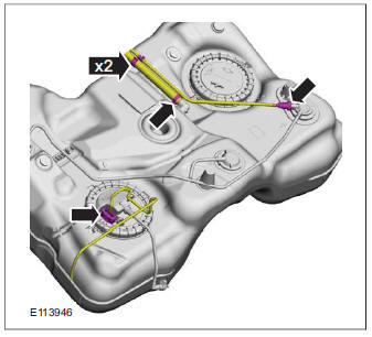
5. Torque: 15 Nm

6. Torque: 15 Nm

7. Torque: 15 Nm

8. Refer to: Fuel Tank Draining (310-00 Fuel System - General Information, General Procedures).
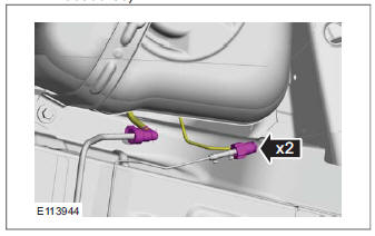
Vehicles with fuel fired booster heater

WARNING: Be prepared to collect escaping fluids.
CAUTION: Use suitable paper to absorb any escaping fluid.
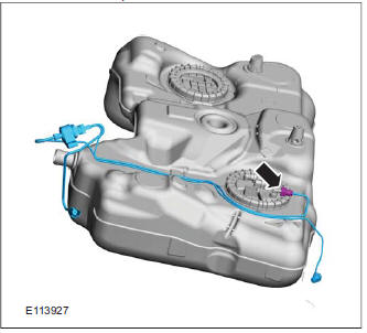
Refer to: Quick Release Coupling (310-00 Fuel System - General Information, General Procedures).
All vehicles
WARNING: Be prepared to collect escaping fluids.
CAUTION: Use suitable paper to absorb any escaping fluid.
Refer to: Quick Release Coupling (310-00 Fuel System - General Information, General Procedures).

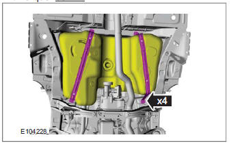
13.Torque: 30 Nm

WARNING: Be prepared to collect escaping fluids.
CAUTION: Use suitable paper to absorb any escaping fluid.
Vehicles with fuel fired booster heater
NOTE: This step is only necessary when installing a new component.
WARNING: Be prepared to collect escaping fluids.
CAUTION: Use suitable paper to absorb any escaping fluid.
Refer to: Quick Release Coupling (310-00 Fuel System - General Information, General Procedures).
All vehicles
NOTE: This step is only necessary when installing a new component.
18. Refer to: Fuel Pump and Sender Unit - 2.5L Duratec (147kW/200PS) - VI5 (310-01 Fuel Tank and Lines, Removal and Installation).
Installation
1. To install, reverse the removal procedure.
Fuel Tank and Lines - 2.5L Duratec (147kW/200PS) - VI5 (Component Location)
Fuel Tank and Lines - 2.5L Duratec (147kW/200PS) - VI5 (Overview)
Fuel Tank - 2.5L Duratec (147kW/200PS) - VI5
Fuel Level Sensor - 2.5L Duratec (147kW/200PS) - VI5
Fuel Tank Filler Pipe
Fuel Filler Nozzle Inhibitor
Fuel Pump and Sender Unit - 2.5L Duratec (147kW/200PS) - VI5
Ford Kuga Service Manual
- General Information
- Jacking and Lifting
- Noise, Vibration and Harshness
- Suspension System - General Information
- Climate Control
- Auxiliary Climate Control
- Instrument Cluster and Panel Illumination
- Instrument Cluster
- Horn
- Warning Devices
- Parking Aid
- Charging System - General Information
- Battery, Mounting and Cables
- Generator and Regulator
- Voltage Converter/Inverter
- Information and Entertainment System - General Information
- Information and Entertainment System
- Exterior Lighting
- Interior Lighting
- Daytime Running Lamps (DRL)
- Module Communications Network
- Module Configuration
- Wiring Harnesses
- Anti-Theft - Active
- Anti-Theft - Passive
- Multifunction Electronic Modules
- Front End Body Panels
- Body Closures
- Interior Trim and Ornamentation
- Exterior Trim and Ornamentation
- Rear View Mirrors
- Seating
- Glass, Frames and Mechanisms
- Instrument Panel and Console
- Handles, Locks, Latches and Entry Systems
- Wipers and Washers
- Bumpers
- Safety Belt System
- Supplemental Restraint System
- Body Repairs - General Information
- Body Repairs - Vehicle Specific Information and Tolerance Checks
- Front End Sheet Metal Repairs
- Roof Sheet Metal Repairs
- Side Panel Sheet Metal Repairs
- Rear End Sheet Metal Repairs
- Paint - General Information
- Uni-Body, Subframe and Mounting System
- Suspension System - General Information
- Front Suspension
- Rear Suspension
- Wheels and Tires
- Driveshaft
- Rear Drive Axle/Differential
- Front Drive Halfshafts
- Rear Drive Halfshafts
- Brake System - General Information
- Front Disc Brake
- Rear Disc Brake
- Parking Brake and Actuation
- Hydraulic Brake Actuation
- Power Brake Actuation
- Anti-Lock Control
- Anti-Lock Control - Stability Assist
- Steering System - General Information
- Power Steering
- Steering Linkage
- Steering Column
- Steering Column Switches
- Engine System - General Information
- Engine- 2.5L Duratec (147kW/200PS) - VI5
- Engine Cooling
- Fuel Charging and Controls-2.5L Duratec (147kW/200PS) - VI5
- Fuel Charging and Controls - Turbocharger- 2.5L Duratec (147kW/200PS) - VI5
- Accessory Drive - 2.5L Duratec (147kW/200PS) - VI5
- Starting System- 2.5L Duratec (147kW/200PS) - VI5
- Engine Ignition - 2.5L Duratec (147kW/200PS) - VI5
- Engine Emission Control - 2.5L Duratec (147kW/200PS) - VI5
- Intake Air Distribution and Filtering - 2.5L Duratec (147kW/200PS) - VI5
- Evaporative Emissions
- Electronic Engine Controls
- Automatic Transmission/Transaxle
- Transmission/Transaxle Cooling
- Automatic Transmission/Transaxle External Controls
- Transfer Case
- Exhaust System-
- Fuel System
- Fuel Tank and Lines
- Acceleration Control
- Speed Control
- Climate Control System
- Climate Control
Main Categories

0.0181