 Ford Kuga Service ManualBody Repairs - General Information
Noise, Vibration and Harshness
Noise, Vibration and Harshness
Noise, coming from the vehicle and which can be heard inside and outside the vehicle.
Vibrations, oscillations that are felt and noticeable inside the vehicle.
Harshness, noises which come from the vehicle and which can be heard, felt and noticed inside and outside the vehicle.
These terms are grouped together under the title Noise, Vibration, Harshness, or NVH for short.
The task of vehicle development and production is to ensure that noises caused by the vehicle do not disturb the driver and passengers. Moreover, the the external noises emitted by the vehicle must not exceed the thresholds set by law.
NOTE: Basic and advanced training courses are offered for the following contents. For an overview of all courses offered, please refer to the Ford Service Organisation's training course brochure.
Noise types and causes
Noises in and around the vehicle are assigned specific descriptions:
- Humming and droning are perceived as low tones.
- Buzzing and whirring are middle tones.
- Howling, whistling, squeaking are assigned to the high tones.
Low to middle tones are considered to be unpleasant. They are palpable and noticeable as oscillations and vibrations throughout the body.
Loud howling and whistling is painful to the ears.
A noise usually consists of a superimposition of different tones which spread as oscillations.
Each of these oscillations has a specific oscillating time and can be measured in frequencies. The frequency describes the number of oscillations per second. The frequency unit is specified in Hertz (Hz).
The human ear can perceive frequencies between 20 and 20000 Hz.
Where the different notes come from in a vehicle:
- Low notes are mostly produced by the engine.
- Low tones can also be produced by the roadbed, particularly on rough surfaces. This is a form of droning which can be felt by the vehicle occupants as vibration or roughness
- High tones however, which are experienced as howling or whistling noises, are often air currents (wind noises) or come from ancillary components such as the generator, power steering pump or drivebelt.
- There are also clattering noises which can occur when driving over an uneven road. These jerking noises are produced by, for example, the shock absorbers, chassis components or loose articles inside the vehicle.
Noises can already be contained where they occur or, if this is not possible, can be confined with suitable measures.
The basic procedures here are the damping of oscillating parts, the insulation of components or the absorption of the noises through appropriate materials.
Damping
If a damper is installed next to an oscillating mass, the characteristic of the damper will reduce the movement of this mass accordingly (e.g. bumper on chassis).
Damping affects the resonance of an object or system.
Isolation
In oscillation technology, the term isolation means decoupling (separation) of components and systems. An engine is mounted in sprung elements, so that as little oscillation as possible is passed to the vehicle.
In automotive technology, the isolation technique used is nearly always rubber mounting. Rubber has a large internal damping capacity. The elasticity of the rubber acts like a spring.
Absorption
Sound waves are reflected from hard surfaces Through the use of absorption material, sound waves hit soft surfaces and are absorbed by them.
The composition and thickness of the material used plays an important role here. A soft surface, depending on its composition, absorbs the sound waves and reduces their energy.
NVH elements
NVH elements are installed to prevent airborne sound transfers to the passenger compartment in different body cavities.
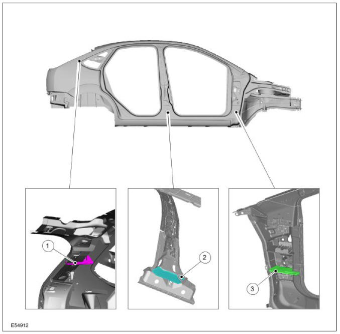
| Item | Description |
| 1 | C-pillar area |
| 2 | B-pillar area |
| 3 | A-pillar area |
On the Focus 2004.75 (07/2004-) these elements are located in the cavities of the A, B and C pillars.
On the estate version, they are also located in the D pillars.
The NVH material consists of a carrier plate which has compressed isolation material at the edges.
In the drying system of the painting equipment used in production, the body is heated to approx. 170 C. At this temperature the isolation material expands to seal the gap between the carrier plate and the bodywork.
NOTE: NVH elements must not be damaged during work on the vehicle body. NVH elements deformed through impact must always be replaced. PU adhesive must always be applied to the edges of new and reused NVH elements during repair work.
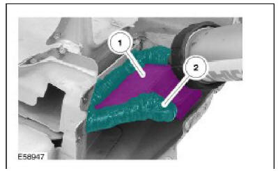
| Item | Description |
| 1 | NVH element |
| 2 | PU adhesive |
For the exact installation position of an NVH element, please refer to the vehicle-specific repair instructions.
If an NVH element is to be reused, the bonding on the body panel must be detached. To do this, the body panel must be heated in the area around the NVH element. The bonding can be detached at approx. 170 C. The damaged panel part can now be carefully dismantled.
Before installing the new panel part, a PU adhesive must be applied to the contact areas between the panel and the NVH element.
Test techniques, measuring devices
The shortest route to an accurate diagnosis results from:
- general information on the problem vehicle and a comparison test with a vehicle of the same construction, without NVH problems.
- vehicle history, including repair history and usage patterns.
- condition history, especially any relationship to repairs or sudden change.
- knowledge of probable causes.
- application of diagnosis procedures in which the vehicle is split into corresponding areas.
The diagnosis and correction of noise, vibration and harshness concerns requires:
- general information on the problem vehicle and a comparison test with a vehicle of the same construction, without NVH problems.
- vehicle history, including repair history and usage patterns.
- condition history, especially any relationship to repairs or sudden change.
- knowledge of probable causes.
- application of diagnosis procedures in which the vehicle is split into corresponding areas.
NOTE: The diagnosis of droning problems is one of the most difficult tasks in the NVH area. With the exception of installed components under stress, a certain diagnosis of droning problems (or boom) on customer vehicles makes great demands on the automotive technician. The performance of measuring equipment and their practice-orientated application can only be obtained through suitable instruction (NVH training). The successful use of these devices requires a great deal of experience on the part of the user.
The diagnosis and correction of noise, vibration and harshness concerns requires:
- a road or system test to determine the exact nature of the concern.
Analysis of possible causes:
- checking of the cause and elimination of the faults found.
- a road test or system test to make sure the concern has been corrected or brought back to within an acceptable range.
- It is often very difficult to locate noises that are audible in the passenger compartment based on the problem description provided by the customer and the road tests performed. The direction of the noise can be detected subjectively, but the source of the noise cannot be found.
NOTE: For a selection of simple test tools, see the wind noises section.
Electronic NVH tester
NOTE: Before using the NVH tester in the service, the service technician should take part in an NVH training course to ensure effective use of this device during the road test. A description of the function and application of the NVH tester is enclosed with the device.
The measuring device described below is used for diagnosis of the solid-borne sound and solid-borne sound transmission paths. The device is particularly suitable for medium and high frequency noise analyses. It principally enables noise diagnosis in the area of solid-borne sound and helps to identify solid-borne sound transmission routes.
In order to obtain a positive diagnosis of droning problems (low frequency noises) and their sources, you must have sufficient experience of how to use this measuring device.
The device works according to the following operating principle: Accelerometers (transmitters) are fitted on various vehicle components or body areas. The signals recorded here can be listened to one after the other on headphones or speakers via the different channels. Simultaneous illustration of several or all measuring channels (for comparison) is only possible visually on the display of the measuring device.
Layout and operation:
- The test device has six different channels for noise diagnosis.
- Each channel is marked in color on the terminal, cable and test device.
- The solid-borne sound recorded is transmitted to the test device or the headphones by the magnetic accelerometers (transmitters).
- There is an amplifier on the test device with which the signal strength and the corresponding channel can be set.
- Only the noises from a transmitter are transferred to the headphones.
- All connected cables can be visually illustrated individually or simultaneously on the display.
- The test device saves the recorded data.
- The recorded data can be imported to a PC and evaluated.
The NVH tester is equipped in addition with mobile magnetic sensors which are particularly suitable for the following noise tests:
- Internal noises at the dashboard
- Engine noise
- Electrical noises (sparking/voltage transmissions)
- Wind noises
- Vacuum - leaks
Chassis noise tester (chassis ear)
Used to diagnose solid-borne sound and its transmission routes. The device is particularly suitable for medium and high frequency noise analysis and principally enables noise diagnosis in the area of solid-borne sound and helps to identify solid-borne sound transmission routes.
In order to obtain a positive diagnosis of droning problems (low frequency noises) and their sources, you must have sufficient experience of how to use this measuring device.
Layout and operation:
The test device has six different channels for noise diagnosis. This means that six microphones equipped with clamps can be attached to different components on the vehicle. The emitted or transmitted solid-borne sound will be transferred from microphone to the headphones. There is an amplifier between the microphone and the headphones at which the signal strengths and the corresponding channel can be set.
Only the noises from one microphone are transferred to the headphones. Each channel is color-coded on the clamp, cable and amplifier.
NOTE: In order to be able to relate the positions of the different microphones during the test process, they are entered in a special test sheet according to "their colors. Microphones, clamps and cables must be carefully routed and attached.
Test process (example for transmission noise):
- Attach microphones to various positions on the transmission or mountings. This first allows the source of the noise to be determined, and then the possible transfer routes.
- A road test can be performed after all the clamps have been attached to the vehicle and all the cables connected to the amplifier.
- Firstly, all the channels are switched through one after the other in neutral, to check the operation of the different channels as well as the noise level in neutral.
- During the road test, all channels are listened to in the different gears, engine speeds, vehicle speeds and loads. This procedural method permits unambiguous diagnosis of the cause of the noise and the route of the noise until it enters the bodywork structure.
- The characteristics of the noise which is the cause of the concern should match those of the noise which is heard. This means compare the sound.
- Depending on the input signal level, there may be a great deal of difference in the noise level in the individual channels.
- Always set the amplifier volume to zero before switching to another channel.
- In order to be able to make any comparisons, the volume settings of the different channels must be recorded on the test sheet.
Description and Usage of Body Repair Literature
Symbols
Health and Safety Precautions
Environmental Regulations
Body Construction
Diagnosis and Damage Evaluation
Body Sheet Metal
Tools and Equipment for Body Repairs
Establish Repair Method
Alignment Check
Straightening
Complete Panel Replacement/Partial Replacement
Corrosion Prevention
Corrosion Damage/Corrosion Repair
Sealer, Underbody Protection Material and Adhesives
Cutting Technique
Panel Beating Technique and Smart Repairs
Paintless Dent Removal
Plastic Repairs
Joining Techniques
Special Repair Techniques
Impact of Insufficient Repair Quality
Water Leaks
Wind Noise
Wind Noise
Noise, Vibration and Harshness
Ford Kuga Service Manual
- General Information
- Jacking and Lifting
- Noise, Vibration and Harshness
- Suspension System - General Information
- Climate Control
- Auxiliary Climate Control
- Instrument Cluster and Panel Illumination
- Instrument Cluster
- Horn
- Warning Devices
- Parking Aid
- Charging System - General Information
- Battery, Mounting and Cables
- Generator and Regulator
- Voltage Converter/Inverter
- Information and Entertainment System - General Information
- Information and Entertainment System
- Exterior Lighting
- Interior Lighting
- Daytime Running Lamps (DRL)
- Module Communications Network
- Module Configuration
- Wiring Harnesses
- Anti-Theft - Active
- Anti-Theft - Passive
- Multifunction Electronic Modules
- Front End Body Panels
- Body Closures
- Interior Trim and Ornamentation
- Exterior Trim and Ornamentation
- Rear View Mirrors
- Seating
- Glass, Frames and Mechanisms
- Instrument Panel and Console
- Handles, Locks, Latches and Entry Systems
- Wipers and Washers
- Bumpers
- Safety Belt System
- Supplemental Restraint System
- Body Repairs - General Information
- Body Repairs - Vehicle Specific Information and Tolerance Checks
- Front End Sheet Metal Repairs
- Roof Sheet Metal Repairs
- Side Panel Sheet Metal Repairs
- Rear End Sheet Metal Repairs
- Paint - General Information
- Uni-Body, Subframe and Mounting System
- Suspension System - General Information
- Front Suspension
- Rear Suspension
- Wheels and Tires
- Driveshaft
- Rear Drive Axle/Differential
- Front Drive Halfshafts
- Rear Drive Halfshafts
- Brake System - General Information
- Front Disc Brake
- Rear Disc Brake
- Parking Brake and Actuation
- Hydraulic Brake Actuation
- Power Brake Actuation
- Anti-Lock Control
- Anti-Lock Control - Stability Assist
- Steering System - General Information
- Power Steering
- Steering Linkage
- Steering Column
- Steering Column Switches
- Engine System - General Information
- Engine- 2.5L Duratec (147kW/200PS) - VI5
- Engine Cooling
- Fuel Charging and Controls-2.5L Duratec (147kW/200PS) - VI5
- Fuel Charging and Controls - Turbocharger- 2.5L Duratec (147kW/200PS) - VI5
- Accessory Drive - 2.5L Duratec (147kW/200PS) - VI5
- Starting System- 2.5L Duratec (147kW/200PS) - VI5
- Engine Ignition - 2.5L Duratec (147kW/200PS) - VI5
- Engine Emission Control - 2.5L Duratec (147kW/200PS) - VI5
- Intake Air Distribution and Filtering - 2.5L Duratec (147kW/200PS) - VI5
- Evaporative Emissions
- Electronic Engine Controls
- Automatic Transmission/Transaxle
- Transmission/Transaxle Cooling
- Automatic Transmission/Transaxle External Controls
- Transfer Case
- Exhaust System-
- Fuel System
- Fuel Tank and Lines
- Acceleration Control
- Speed Control
- Climate Control System
- Climate Control
Main Categories

0.0157