 Ford Kuga Service ManualAnti-Lock Control - Stability Assist » Anti-Lock Control - Stability Assist (System Operation and Component
Description)
Ford Kuga Service ManualAnti-Lock Control - Stability Assist » Anti-Lock Control - Stability Assist (System Operation and Component
Description)
System Diagram
Ford Kuga
Service Manual
System Diagram
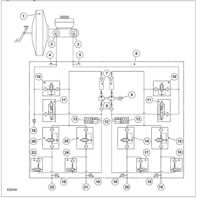
| Item | Description |
| 1 | Brake booster |
| 2 | Primary hydraulic circuit |
| 3 | Secondary hydraulic circuit |
| 4 | Pulsation damper |
| 5 | Pulsation damper |
| 6 | engine control module |
| 7 | Damping chamber |
| 8 | Dual circuit hydraulic pump |
| 9 | D.C. motor |
| 10 | Solenoid-operated pilot valve (2 off) |
| 11 | Solenoid-operated priming valve (2 off) |
| 12 | One way check valve |
| 13 | Low-pressure accumulator (2 off) |
| 14 | Solenoid-operated inlet valve (RH rear brake) |
| 15 | Solenoid-operated inlet valve (LH front brake) |
| 16 | Solenoid-operated outlet valve (LH front brake) |
| 17 | Solenoid-operated outlet valve (RH rear brake) |
| 18 | Pressure sensor (5 off) |
| 19 | LH front brake (secondary circuit) |
| 20 | RH rear brake (secondary circuit) |
| 21 | LH rear brake (primary circuit) |
| 22 | RH front brake (primary circuit) |
| 23 | Solenoid-operated outlet valve (RH front brake) |
| 24 | Solenoid-operated outlet valve (LH rear brake) |
| 25 | Solenoid-operated inlet valve (LH rear brake) |
| 26 | Solenoid-operated inlet valve (RH front brake) |
More about «Anti-Lock Control - Stability Assist (System Operation and Component
Description)»:
System Diagram
System Operation
Component Description
Ford Kuga Service Manual
- General Information
- Jacking and Lifting
- Noise, Vibration and Harshness
- Suspension System - General Information
- Climate Control
- Auxiliary Climate Control
- Instrument Cluster and Panel Illumination
- Instrument Cluster
- Horn
- Warning Devices
- Parking Aid
- Charging System - General Information
- Battery, Mounting and Cables
- Generator and Regulator
- Voltage Converter/Inverter
- Information and Entertainment System - General Information
- Information and Entertainment System
- Exterior Lighting
- Interior Lighting
- Daytime Running Lamps (DRL)
- Module Communications Network
- Module Configuration
- Wiring Harnesses
- Anti-Theft - Active
- Anti-Theft - Passive
- Multifunction Electronic Modules
- Front End Body Panels
- Body Closures
- Interior Trim and Ornamentation
- Exterior Trim and Ornamentation
- Rear View Mirrors
- Seating
- Glass, Frames and Mechanisms
- Instrument Panel and Console
- Handles, Locks, Latches and Entry Systems
- Wipers and Washers
- Bumpers
- Safety Belt System
- Supplemental Restraint System
- Body Repairs - General Information
- Body Repairs - Vehicle Specific Information and Tolerance Checks
- Front End Sheet Metal Repairs
- Roof Sheet Metal Repairs
- Side Panel Sheet Metal Repairs
- Rear End Sheet Metal Repairs
- Paint - General Information
- Uni-Body, Subframe and Mounting System
- Suspension System - General Information
- Front Suspension
- Rear Suspension
- Wheels and Tires
- Driveshaft
- Rear Drive Axle/Differential
- Front Drive Halfshafts
- Rear Drive Halfshafts
- Brake System - General Information
- Front Disc Brake
- Rear Disc Brake
- Parking Brake and Actuation
- Hydraulic Brake Actuation
- Power Brake Actuation
- Anti-Lock Control
- Anti-Lock Control - Stability Assist
- Steering System - General Information
- Power Steering
- Steering Linkage
- Steering Column
- Steering Column Switches
- Engine System - General Information
- Engine- 2.5L Duratec (147kW/200PS) - VI5
- Engine Cooling
- Fuel Charging and Controls-2.5L Duratec (147kW/200PS) - VI5
- Fuel Charging and Controls - Turbocharger- 2.5L Duratec (147kW/200PS) - VI5
- Accessory Drive - 2.5L Duratec (147kW/200PS) - VI5
- Starting System- 2.5L Duratec (147kW/200PS) - VI5
- Engine Ignition - 2.5L Duratec (147kW/200PS) - VI5
- Engine Emission Control - 2.5L Duratec (147kW/200PS) - VI5
- Intake Air Distribution and Filtering - 2.5L Duratec (147kW/200PS) - VI5
- Evaporative Emissions
- Electronic Engine Controls
- Automatic Transmission/Transaxle
- Transmission/Transaxle Cooling
- Automatic Transmission/Transaxle External Controls
- Transfer Case
- Exhaust System-
- Fuel System
- Fuel Tank and Lines
- Acceleration Control
- Speed Control
- Climate Control System
- Climate Control
Main Categories

© 2017-2025 Copyright www.fokuman.com
0.015
0.015