 Ford Kuga Service ManualAnti-Lock Control - Stability Assist » Anti-Lock Control - Stability Assist (System Operation and Component
Description)
Ford Kuga Service ManualAnti-Lock Control - Stability Assist » Anti-Lock Control - Stability Assist (System Operation and Component
Description)
System Operation
System Operation
The HCU features 3 operating modes:
Normal braking: Initially, no current is supplied to any of the solenoid-operated valves. Operating the brake pedal produces a corresponding increase or decrease of pressure in the brakes, through the open pilot valves and inlet valves. If the ABS module determines that EBD is necessary, it energizes the inlet valves for both the rear brakes, to isolate the brakes from any further increase in hydraulic pressure.
ABS braking:If the ABS module determines that ABS braking is necessary, it actuates the inlet and outlet valves of the relevant brake and starts the hydraulic return pump. The inlet valve closes to isolate the brake from pressurized fluid; the outlet valve opens to release pressure from the brake into the accumulator and the return pump circuit.
The brake releases slightly and the wheel starts to turn again. The ABS control unit then operates the inlet and outlet valves to regulate the hydraulic pressure acting on the brake in order to maximize braking effect without the wheel locking up. Control of the valves for each wheel takes place individually.
Active braking: With active braking, pressure is generated for other braking functions than the normal and ABS braking systems, e.g. for the ESP and TCS systems. For active braking, the ABS module energizes the pilot valves and priming valves, starts the return pump and energizes all of the inlet valves. Brake fluid, drawn from the reservoir through the master cylinder and priming valve, is pressurized by the return pump and supplied to the inlet valves. The ABS control unit then actuates the inlet and outlet valves in order to regulate the pressure for the individual brakes.
Some noise may be generated during active braking.
PRINCIPLES OF OPERATION
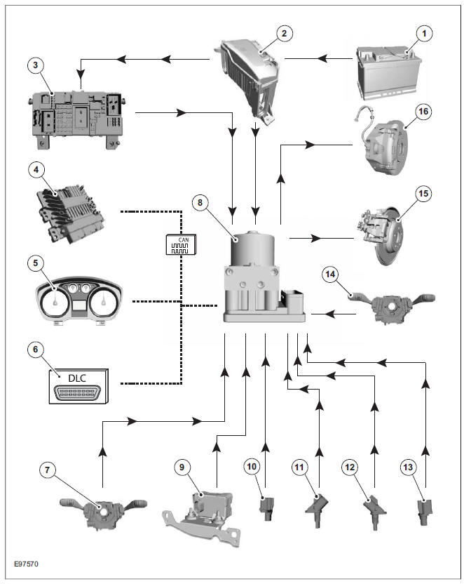
| Item | Description |
| 1 | Battery |
| 2 | Battery junction box (BJB) in the engine compartment |
| 3 | Generic electronic module (GEM) |
| 4 | Powertrain Control Module (PCM) |
| 5 | Instrument cluster |
| 6 | Data link connector (DLC) |
| 7 | Steering Wheel Rotation Sensor |
| 8 | ABS/ESP module or hydraulic control unit (HCU) |
| 9 | Combined yaw rate sensor and lateral acceleration sensor / longitudinal acceleration sensor |
| 10 | Front wheel sensor |
| 11 | Rear wheel sensor |
| 12 | Rear wheel sensor |
| 13 | Front wheel sensor |
| 14 | ESP switch |
| 15 | Rear brakes |
| 16 | Front brake |
The ABS monitors the different wheel speeds of the vehicle with the aid of wheel speed sensors.
Using the data from all of the wheel speed sensors, the ABS module calculates the so-called reference speed, which is a measure of the actual road speed. The ABS module compares the individual circumferential wheel speeds with this reference speed when the driver initiates braking. If one or more of the circumferential wheel speeds deviates too far from the reference speed, this means that slip at the affected wheels is so great that steering stability of the vehicle is no longer ensured. The ABS module actuates electro-mechanical valves which influence the brake pressure at the relevant wheels.
Like the traction control system (TCS), the ESP system uses a large proportion of the ABS components. In addition, there are sensors which pick up the steering angle, the acceleration forces acting on the vehicle and the yaw rate or yaw moment. The sensors transmit these signals to the combined ABS/ESP module. Using the wheel speed and steering angle data, the ABS/ESP module calculates the direction of travel planned by the driver and determines the corresponding speed-dependent lateral acceleration and yaw moment. These values are compared with those actual measured. If the actual lateral acceleration and the yaw moment deviate excessively from the target values (unstable driving characteristics), the ABS/ESP module actuates individual brakes selectively via the HCU (hydraulic control unit). In addition, the engine speed is reduced by intervention in the engine management system.
How the system works for understeer: In the event of understeer, brake intervention occurs at the wheels on the inside of the curve. The rear wheel is braked heavily, so that a high amount of slip is caused. In this way, the cornering force of the rear axle is heavily reduced and the centrifugal force that now becomes effective turns the rear of the vehicle back into the curve. The front wheel is not braked as hard. The braking force that is transmitted via the front wheel to the road surface generates a torque with the aid of the lever arm (vertical tire force to the vehicle's centre of gravity), which supports the yaw moment of the vehicle.
Both measures together result in the vehicle reverting back to the curved path intended by the driver.
How the system works for oversteer: In the event of oversteer the wheels on the outside of the curve are braked. This time, the front wheel is subjected to a high level of slip so that the cornering force at the front axle is reduced. The rear wheel is not braked as heavily and, together with the effective lever arm, results in a reduction in the vehicle yaw moment. Both measures together result in the vehicle being stabilized and reverting back to the curved path intended by the driver.
If ESP control occurs, possible ABS interventions will be overridden as the ESP works at higher slip rates than the ABS.
Emergency brake assist (EBA): The emergency brake assist helps drivers in emergency braking situations by automatically applying the brakes with the maximum possible braking force.
If the brake pedal is pressed very suddenly, the ABS module increases the hydraulic pressure to all of the brakes until the threshold for ABS intervention is reached. This applies the maximum braking effort for the available traction. The ABS control unit monitors inputs from the brake pedal switch and from the pressure sensor within the HCU to check for sudden actuation of the brakes.
With the brake pedal pressed, the ABS module triggers emergency braking if the rate of increase of hydraulic pressure exceeds the predetermined limit.
If the brake pedal is pressed so hard that the ABS becomes active on the front wheels then the ABS control unit increases the pressure to the rear wheel brakes up to the ABS intervention threshold.
EBA operation continues until the driver releases the brake pedal sufficiently for the hydraulic pressure in the HCU to drop below a threshold value stored in the ABS module.
Trailer stability control: If the vehicle is ordered with a trailer coupling then the Trailer Stability Control function is integrated in the ESP. The ESP detects snaking when driving with a trailer and reduces the speed of the vehicle and trailer through adapted braking and, if necessary, by also reducing the engine output until the snaking movement of the trailer is corrected.
Roll-over protection: The ESP dynamically determines the tipping tendency of the vehicle and works in conjunction with the EBA system to prevent the vehicle from tipping over during dynamic maneuvers like lane changing or while negotiating bends.
Emergency brake light:The emergency brake light automatically switches on the hazard flasher system to warn drivers of other vehicles that emergency braking is being initiated. Based on a defined delay value, the ABS/ESP module sends a signal to the generic electronic module (GEM) via the CAN data bus. The GEM activates the hazard flasher system, that then flashes 7 times.
Prerequisites for activation of the emergency brake light are:
- The speed is higher than 50 km/h.
- The brake pedal is being actuated.
- The deceleration is greater than 9 m/s².
To prevent activation on snow or ice, for example, the following prerequisites must be met:
- The speed is higher than 50 km/h.
- The brake pedal is being actuated.
- ABS regulation takes place.
- The deceleration is greater than 6 m/s².
Tire pressure monitoring system:The tire pressure monitoring system used in the Kuga is able to detect loss of air in a tire at an early stage and warn the driver. Because it can only compare the behaviour of the tyres with each other, it is not possible to draw conclusions about the absolute tyre pressure. It is also not possible to monitor the spare tyre pressure. In order for the system to operate correctly, the tyre pressures must be regularly checked and corrected and the system subsequently initialised (see below).
The tire pressure monitoring system used here, depending on the equipment level, is built into the anti-lock braking system (ABS) as an extra function and therefore does not have its own sensors.
The ABS module measures the loss of pressure in the tyres by calculation using the wheel speed sensors of the ABS system. If a tyre loses pressure, its diameter decreases and the speed of the wheel therefore increases. If the ABS module detects such a loss in pressure, it sends a signal to the instrument cluster via the CAN bus and a warning message is displayed in the message centre. The warning threshold depends among other things on the dimension of the tyres being used, the vehicle operating conditions and the status at the last initialisation. Since neither the absolute tyre pressure nor the position of the tyre is known, the pressure of all the tyres must be checked and the system re-initialised after a tyre pressure warning. If necessary, the cause of the loss of pressure must be investigated.
Regular tyre pressure checks are still necessary.
The system must be initialised after a tyre is changed, winter or summer tyres fitted, the pressures corrected or adjusted to suit the vehicle load. This can be done by the driver using the driver information system. For further information, see: Owner's Manual.
System Diagram
System Operation
Component Description
Ford Kuga Service Manual
- General Information
- Jacking and Lifting
- Noise, Vibration and Harshness
- Suspension System - General Information
- Climate Control
- Auxiliary Climate Control
- Instrument Cluster and Panel Illumination
- Instrument Cluster
- Horn
- Warning Devices
- Parking Aid
- Charging System - General Information
- Battery, Mounting and Cables
- Generator and Regulator
- Voltage Converter/Inverter
- Information and Entertainment System - General Information
- Information and Entertainment System
- Exterior Lighting
- Interior Lighting
- Daytime Running Lamps (DRL)
- Module Communications Network
- Module Configuration
- Wiring Harnesses
- Anti-Theft - Active
- Anti-Theft - Passive
- Multifunction Electronic Modules
- Front End Body Panels
- Body Closures
- Interior Trim and Ornamentation
- Exterior Trim and Ornamentation
- Rear View Mirrors
- Seating
- Glass, Frames and Mechanisms
- Instrument Panel and Console
- Handles, Locks, Latches and Entry Systems
- Wipers and Washers
- Bumpers
- Safety Belt System
- Supplemental Restraint System
- Body Repairs - General Information
- Body Repairs - Vehicle Specific Information and Tolerance Checks
- Front End Sheet Metal Repairs
- Roof Sheet Metal Repairs
- Side Panel Sheet Metal Repairs
- Rear End Sheet Metal Repairs
- Paint - General Information
- Uni-Body, Subframe and Mounting System
- Suspension System - General Information
- Front Suspension
- Rear Suspension
- Wheels and Tires
- Driveshaft
- Rear Drive Axle/Differential
- Front Drive Halfshafts
- Rear Drive Halfshafts
- Brake System - General Information
- Front Disc Brake
- Rear Disc Brake
- Parking Brake and Actuation
- Hydraulic Brake Actuation
- Power Brake Actuation
- Anti-Lock Control
- Anti-Lock Control - Stability Assist
- Steering System - General Information
- Power Steering
- Steering Linkage
- Steering Column
- Steering Column Switches
- Engine System - General Information
- Engine- 2.5L Duratec (147kW/200PS) - VI5
- Engine Cooling
- Fuel Charging and Controls-2.5L Duratec (147kW/200PS) - VI5
- Fuel Charging and Controls - Turbocharger- 2.5L Duratec (147kW/200PS) - VI5
- Accessory Drive - 2.5L Duratec (147kW/200PS) - VI5
- Starting System- 2.5L Duratec (147kW/200PS) - VI5
- Engine Ignition - 2.5L Duratec (147kW/200PS) - VI5
- Engine Emission Control - 2.5L Duratec (147kW/200PS) - VI5
- Intake Air Distribution and Filtering - 2.5L Duratec (147kW/200PS) - VI5
- Evaporative Emissions
- Electronic Engine Controls
- Automatic Transmission/Transaxle
- Transmission/Transaxle Cooling
- Automatic Transmission/Transaxle External Controls
- Transfer Case
- Exhaust System-
- Fuel System
- Fuel Tank and Lines
- Acceleration Control
- Speed Control
- Climate Control System
- Climate Control
Main Categories

0.0158