 Ford Kuga Service ManualSeating » Seats (System Operation and Component Description)
System Operation
Ford Kuga
Service Manual
System Operation
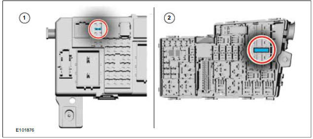
The switch group for the electrically adjustable driver's seat is supplied by the GEM and the EJB with a permanent voltage supply.
| Item | Description |
| 1 | Fuse GEM |
| 2 | Fuse EJB |
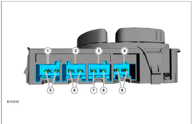
Both supply lines of all three servo motors are separately connected to the switch group for the electrically adjustable driver's seat.
| Item | Description |
| 1 | Output, seat servo motor, forward/back |
| 2 | Output, backrest servo motor, forward/back |
| 3 | Input, switch group for electrically adjustable driver's seat |
| 4 | Output, seat servo motor, up/down |
| 5 | Supply lines, seat servo motor, forward/back |
| 6 | Supply lines, backrest servo motor, forward/back |
| 7 | Ground supply, switch group for electrically adjustable driver's seat |
| 8 | Voltage supply, switch group for electrically adjustable driver's seat |
| 9 | Supply lines, seat servo motor, up/down |
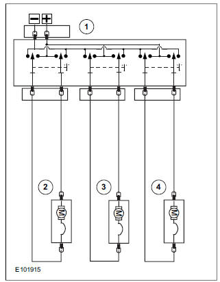
When the switch is pressed, voltage and ground are connected to both of the supply lines of the selected servo motor. In the process, the polarity changes depending on the switch position and therefore the direction of rotation of the relevant servo motor.
| Item | Description |
| 1 | Switch group for electrically adjustable driver's seat |
| 2 | Seat servo motor, up/down |
| 3 | Backrest servo motor, forward/back |
| 4 | Seat servo motor, forward/back |
More about «Seats (System Operation and Component Description)»:
System Diagram
System Operation
Component Description
Ford Kuga Service Manual / Seating / Seats (System Operation and Component Description) / System Operation
Ford Kuga Service Manual
- General Information
- Jacking and Lifting
- Noise, Vibration and Harshness
- Suspension System - General Information
- Climate Control
- Auxiliary Climate Control
- Instrument Cluster and Panel Illumination
- Instrument Cluster
- Horn
- Warning Devices
- Parking Aid
- Charging System - General Information
- Battery, Mounting and Cables
- Generator and Regulator
- Voltage Converter/Inverter
- Information and Entertainment System - General Information
- Information and Entertainment System
- Exterior Lighting
- Interior Lighting
- Daytime Running Lamps (DRL)
- Module Communications Network
- Module Configuration
- Wiring Harnesses
- Anti-Theft - Active
- Anti-Theft - Passive
- Multifunction Electronic Modules
- Front End Body Panels
- Body Closures
- Interior Trim and Ornamentation
- Exterior Trim and Ornamentation
- Rear View Mirrors
- Seating
- Glass, Frames and Mechanisms
- Instrument Panel and Console
- Handles, Locks, Latches and Entry Systems
- Wipers and Washers
- Bumpers
- Safety Belt System
- Supplemental Restraint System
- Body Repairs - General Information
- Body Repairs - Vehicle Specific Information and Tolerance Checks
- Front End Sheet Metal Repairs
- Roof Sheet Metal Repairs
- Side Panel Sheet Metal Repairs
- Rear End Sheet Metal Repairs
- Paint - General Information
- Uni-Body, Subframe and Mounting System
- Suspension System - General Information
- Front Suspension
- Rear Suspension
- Wheels and Tires
- Driveshaft
- Rear Drive Axle/Differential
- Front Drive Halfshafts
- Rear Drive Halfshafts
- Brake System - General Information
- Front Disc Brake
- Rear Disc Brake
- Parking Brake and Actuation
- Hydraulic Brake Actuation
- Power Brake Actuation
- Anti-Lock Control
- Anti-Lock Control - Stability Assist
- Steering System - General Information
- Power Steering
- Steering Linkage
- Steering Column
- Steering Column Switches
- Engine System - General Information
- Engine- 2.5L Duratec (147kW/200PS) - VI5
- Engine Cooling
- Fuel Charging and Controls-2.5L Duratec (147kW/200PS) - VI5
- Fuel Charging and Controls - Turbocharger- 2.5L Duratec (147kW/200PS) - VI5
- Accessory Drive - 2.5L Duratec (147kW/200PS) - VI5
- Starting System- 2.5L Duratec (147kW/200PS) - VI5
- Engine Ignition - 2.5L Duratec (147kW/200PS) - VI5
- Engine Emission Control - 2.5L Duratec (147kW/200PS) - VI5
- Intake Air Distribution and Filtering - 2.5L Duratec (147kW/200PS) - VI5
- Evaporative Emissions
- Electronic Engine Controls
- Automatic Transmission/Transaxle
- Transmission/Transaxle Cooling
- Automatic Transmission/Transaxle External Controls
- Transfer Case
- Exhaust System-
- Fuel System
- Fuel Tank and Lines
- Acceleration Control
- Speed Control
- Climate Control System
- Climate Control
Main Categories

© 2017-2026 Copyright www.fokuman.com
0.0247
0.0247