 Ford Kuga Service ManualElectronic Engine Controls » Electronic Engine Controls (System Operation and Component Description)
Component Description
Component Description
PCM
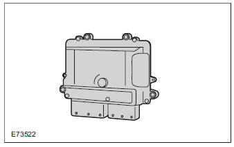
A voltage transformer integrated into the PCM provides various components of the PCM and sensors on the engine with a 5 volt supply.
Functions which work at battery voltage, such as the injectors, are controlled via internal power end stages or, like the ignition coils, via external power end stages in the ignition coils themselves.
CMP
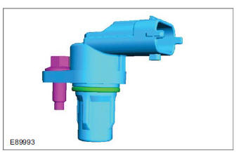
The intake and exhaust camshafts each have a sensor installed on them.
The CMP sensor is realized as a Hall effect sensor and is provided by the PCM with a 5 volt supply.
The Hall effect sensor emits a signal when the pulse segments incorporated into the sensor wheel rotate past the tip of the sensor. If an increase occurs in the area of the sensor, the PCM receives a 'high' signal with a maximum voltage of 4.5V. If a gap occurs in the area of the sensor, a 'low' signal is sent to the PCM. Here the voltage is approx. 0.5V.
CKP sensor
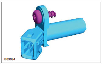
The CKP sensor utilizes the induction principle. A sinusoidal voltage is sent to the PCM. When performing a voltage test, ensure that the CKP sensor is connected to the engine wiring harness This is necessary, otherwise the sensor will not be subjected to any load and incorrect measurements will result.
KS
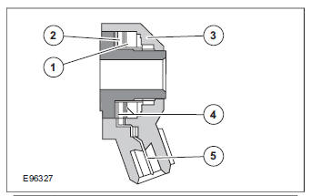
| Item | Description |
| 1 | Seismic mass |
| 2 | Piezoceramic |
| 3 | Housing |
| 4 | Piezoceramic contact |
| 5 | Electrical connection |
The KS converts mechanical vibrations of the cylinder block into electrical pulses which can then be processed by the PCM.
The KS consists of piezo-ceramic crystals that generate a voltage when subjected to a mechanical load.
When fastening the KS, make sure the specified torque is adhered to. In this way a defined initial tension is applied to the crystals which exerts an influence on the operation of the KS.
When the engine is running, the pressure fluctuations arising due to the combustion process cause vibrations in the cylinder block. These act on the crystals in the KS, causing the sensors to produce an output signal. The stronger the vibrations, the higher the frequency and the AC voltage. These signals are evaluated by the PCM and compared with stored data.
| Item | Description |
| A | Normal combustion |
| B | Knocking combustion |
| 1 | Pressure characteristic in cylinder |
| 2 | Output signal from KS |
Broadband HO2S
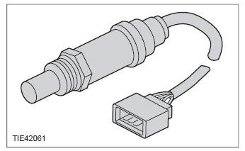
The planar broadband HO2S also allows measurements of the exhaust gas which deviates from the stoichiometric ratio (lambda = 1). The measuring range extends from lambda 0.7 to 2.8, whereby the broadband HO2S emits a clear, constant signal.
The broadband HO2S consists of a Nernst concentration cell and an oxygen pump cell, which transports the oxygen ions.
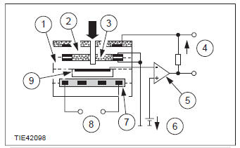
| Item | Description |
| 1 | Nernst concentration cell |
| 2 | Oxygen pump cell |
| 3 | Measuring area |
| 4 | Pump current |
| 5 | Regulating switch |
| 6 | Reference voltage |
| 7 | Heater |
| 8 | Heating voltage |
| 9 | Reference air duct |
Between the oxygen pump cell and the Nernst measuring electrode, there is a diffusion gap which acts as the measuring area and is connected to the exhaust gas. The Nernst concentration cell is connected via a duct with the ambient reference air and the measuring area. It detects the mixture composition in the measuring area. A concentration of lambda = 1 is set in the measuring area using the oxygen ion flow. This is done by applying a reference voltage which results in a pump current.
When the exhaust gas is lean, the oxygen pump cell is actuated in such a way that oxygen ions are pumped out of the measuring area. This is detected by the regulating switch, so that the flow can move (positive direction).
If the exhaust gas is rich, then the current direction is reversed, i.e. the cell pumps oxygen ions into the measuring area. The regulating switch detects this, so the flow is reversed (negative direction).
| Item | Description |
| Ip | Pump current in mA |
| 1 | positive pump current |
| 2 | negative pump current |
The pump current represents a direct measurement of the mixture composition. With lambda 1 (14.7 kg air/1 kg fuel), the pump current is 0 mA. The relatively small measured current is converted into a voltage signal in the PCM using an evaluation circuit. The heating of the broadband HO2S is supplied with a reference voltage of 11 to 14V. The operating temperature of the broadband HO2S is 650 - 900 C.
The characteristic curve of the broadband HO2S is constant (linear), without a lambda jump.
VCT (variable camshaft timing) solenoids
The camshaft adjustment solenoids are multi-way solenoid valves that are actuated with a PWM signal, thereby allowing the valve plungers to be steplessly adjusted.
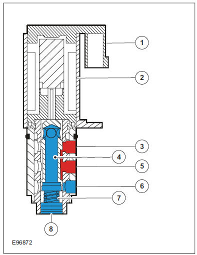
| Item | Description |
| 1 | Electrical connection |
| 2 | Solenoid coil |
| 3 | Engine oil pressure supply bore and ring groove for camshaft adjustment unit chamber A |
| 4 | Tappet |
| 5 | Engine oil pressure supply bore for camshaft adjustment solenoid |
| 6 | Engine oil pressure supply bore and ring groove for camshaft adjustment unit chamber B |
| 7 | Spring |
| 8 | Engine oil return bore |
MAF sensor
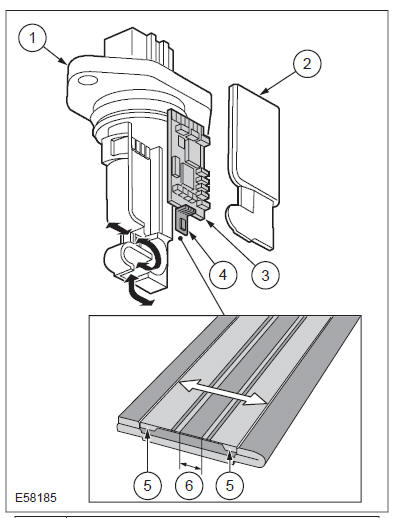
| Item | Description |
| 1 | Housing |
| 2 | Housing cover |
| 3 | Control electronics |
| 4 | Sensor element |
| 5 | Sensor measuring cell |
| 6 | Heating zone |
The MAF sensor works on the 'hot-film principle'.
The MAF sensor is powered via the Powertrain Control Module relay in the BJB. The MAF sensor is connected to ground via the PCM.
The MAF sensor sits in a molded part which protrudes into the center of the air cleaner's outlet pipe. From this position, it measures the air mass drawn in by the engine.
The air mass aspirated by the engine is determined on the basis of the cooling effect of the intake air via a hot-film element in the MAF sensor. The greater the aspirated air mass, the greater the cooling effect and the lower the electrical resistance of the hot-film element. The electronics in the MAF sensor process this resistance value and send a voltage signal to the PCM corresponding to the aspirated air mass.
This analogue voltage signal is between 0.5V and 5V. Low mass of intake air produces a low voltage signal. A high mass of intake air produces a correspondingly high voltage signal.
The MAF sensor is also capable of detecting the backflow of the intake air. A sensor element is heated electrically on the integrated chip and then cooled by the air flowing through. The regulating switch supplies the heating current in such a way that it attains a constant excess temperature in comparison to the intake air. The mass air flow and the direction of flow can be derived from this heating current (given in the form of a signal voltage). Below a certain voltage value there is a return flow. The direction is flow is registered by two sensors pointing in different directions. The measurement does not require a great deal of software processing effort, even with a strongly pulsating mass air flow.
MAPT
The MAPT sensor combines two sensors in one housing. These are the MAP sensor and the IAT sensor. They take the form of a piezoelectric resistor and an NTC resistor.
The MAP sensor receives a reference voltage of 5V from the PCM. The output signal from the MAP sensor element is an analog voltage signal which changes proportionately to the prevailing pressure in the intake manifold.
The IAT sensor records the temperature of the intake air downstream of the intercooler.
APP sensor
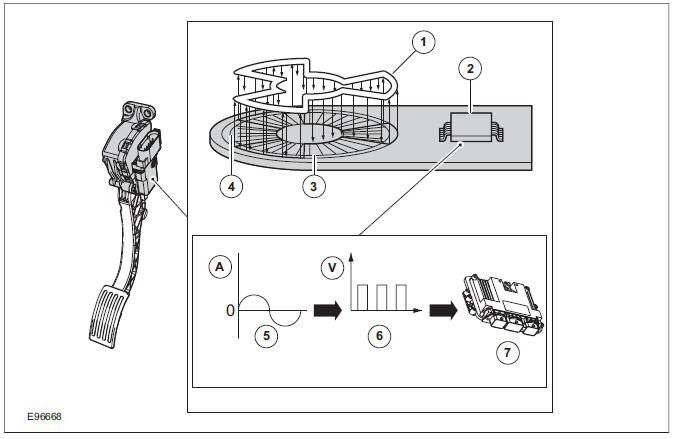
| Item | Description |
| A | Amperes |
| V | Volts |
| 1 | Valve rotor |
| 2 | Electronics |
| 3 | Primary coil |
| 4 | Secondary coil |
| 5 | Analog alternating current |
| 6 | Generated PWM signal. |
| 7 | PCM Comments: PWM signal is converted in the GEM and forwarded via the CAN data bus. |
The APP sensor is a double contactless inductive sensor. The APP sensor is integrated with the accelerator pedal in the accelerator pedal module.
The inductive sensor essentially works in a similar way to a transformer. The incoming DC voltage first has to be converted into AC voltage.
Depressing the accelerator pedal moves a rotor.
This induces the AC voltage from the primary coil into the secondary coil. The strength of the induction depends on the position of the rotor:
- no accelerator-pedal actuation: low induction, i.e. low amplitude of the AC voltage,
- full accelerator-pedal actuation: high induction, i.e., high amplitude of the AC voltage.
To allow the PCM to process the AC voltage signal output by the secondary coil, the signal must first be converted into a PWM signal in the sensor electronics.
In the APP sensor the signals are split as follows:
- APP 1 = PWM signal to the GEM and from there via the CAN data bus to the PCM.
- APP 2 = the analogue DC (direct current) signal is sent directly to the PCM.
Both signals are monitored by the PCM for plausibility.
CPP sensor
The sensor works on the Hall-effect principle and records the position of the piston in the master cylinder without contact. The permanent magnet required for recording the position is located in the piston of the clutch master cylinder.
The signal from the CPP sensor is recorded by the GEM and transmitted to the CAN via the PCM bus.
BPP switches
The BPP switch is designed as normally-closed contact. In its rest state the switch is closed and sends an earth signal to the GEM.
The brake light switch is designed as normally-open contact and is open in its rest state.
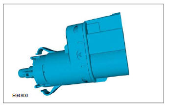
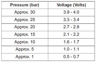
Air conditioning (A/C) pressure sensor
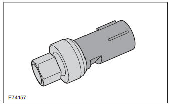
The A/C pressure sensor is installed on the high-pressure side of the A/C. The input voltage is 5V, the output voltage is between 0.5V and 4.5V depending on the cryogenic fluid pressure. When the cryogenic fluid pressure is low, the output voltage is also low.
Throttle control unit
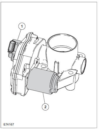
| Item | Description |
| 1 | TP sensor |
| 2 | Electric motor |
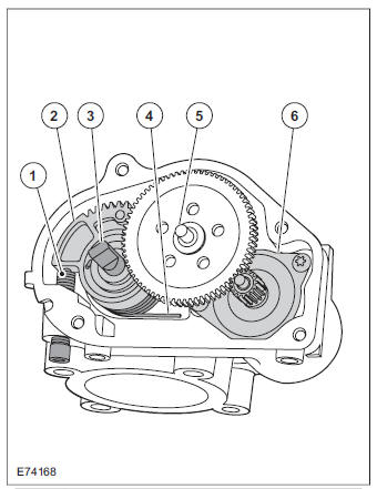
| Item | Description |
| 1 | Stop screw |
| 2 | Toothed segment |
| 3 | Throttle flap spindle |
| 4 | Throttle flap return spring |
| 5 | Joint shaft |
| 6 | Electric motor with pinion |
CAUTION: The throttle control unit must not be repaired or adjusted. The stop of the throttle valve must on no account be adjusted.
If there is a fault, the throttle is returned to its original position by means of the throttle valve return spring. In this position, the throttle valve is still slightly open. As a result, a higher idle speed is set, enabling the vehicle to be driven, though within narrow limits.
ECT sensor
The ECT sensor is designed as an NTC resistor.
A voltage of 5V is applied to the ECT sensor by the PCM. The PCM is able to determine the coolant temperature from the temperature-dependent voltage drop at the sensor.
Cooling fan module
The cooling fan module is directly supplied with battery power via a 60A fuse in the BJB. The radiator fan speed is controlled by the PWM via a PCM signal.
Injectors
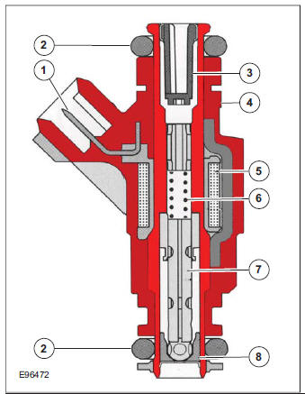
| Item | Description |
| 1 | Electrical connector |
| 2 | Seal |
| 3 | Fuel inlet with fine sieve |
| 4 | Housing |
| 5 | Coil |
| 6 | Spring |
| 7 | Valve needle with solenoid armature |
| 8 | Valve seat with nozzle hole disk |
The fuel injectors consist of a housing with fuel passages, a coil and an injector needle with a solenoid armature. The fuel inlet in the injector features a fine sieve. There are two holes in the nozzle hole disk. These are arranged so that two jets of fuel emerge. Each jet supplies one intake valve of the respective cylinder.
Ignition coil-on-plug
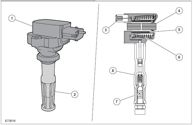
| Item | Description |
| 1 | Coil-on-plug ignition coil |
| 2 | Spark plug connector |
| 3 | Low-voltage connection |
| 4 | Laminated soft-iron core |
| 5 | Primary winding |
| 6 | Secondary winding |
| 7 | Spark plug |
| 8 | High-voltage connection via spring contact |
In an ignition system with coil-on-plug ignition coils, each cylinder is actuated individually and only once per cycle (working stroke). The coil-on-plug ignition coils are mounted directly on the spark plugs, therefore no ignition cables are required between the ignition coils and the spark plugs.
Each individual ignition coil is actuated on the low-voltage side by the PCM. The power end-stages are incorporated into the coil-on-plug ignition coils. Only the actuating current for these power end-stages is controlled by the PCM.
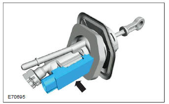
Fuel pressure/fuel temperature sensor
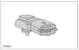
The fuel pressure/fuel temperature sensor is a combination of two sensors, one for the fuel absolute pressure and one for the fuel temperature.
The sensors register the fuel values in the fuel injection supply manifold. The sensor is supplied with a 5V voltage by the PCM.
The fuel pressure sensor is a piezoresistor and works using an analog signal. The change in output voltage mirrors the change in pressure in the fuel rail. If the pressure is low, the output voltage is also low.
The fuel temperature sensor is an NTC resistor.
When the fuel pressure/fuel temperature sensor is
disconnected, the resistance of the fuel
temperature sensor between connections 1 and 2
of the sensor can be measured. 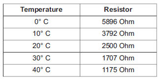
The values of the fuel pressure/fuel temperature sensor can be read out with IDS. The displayed values are absolute values (fuel pressure + atmospheric pressure).
Wastegate control valve
The boost control solenoid valve is a 2/3-way valve that is actuated with a PWM signal. This allows the valve opening to be steplessly adjusted.
Power (battery voltage) is supplied via the Powertrain Control Module relay in the BJB. The solenoid coil resistance is around 23 ohms at 20 C.
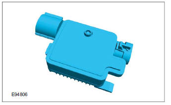
Engine oil level, temperature and quality sensor
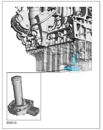
The sensor is a combined oil level and oil temperature sensor.
The sensor consists of:
- Electrical connector
- Integral electronics
- PTC resistor
- Capacitive element consisting of two tubes with a space between them. The one tube represents the positive side, the other the negative. The oil between the tubes creates the capacitive properties.
The sensor receives a 5V voltage from the PCM.
The sensor generates a PWM signal that is sent to the PCM.
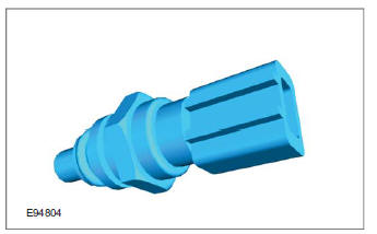
Exterior aor temperature sensor
The outside air temperature sensor is a NTC resistor and is supplied with a 5V voltage by the PCM.
The resistance of, and consequently the voltage from, the outside air temperature sensor changes as a function of temperature.
System Diagram
System Operation
Component Description
Ford Kuga Service Manual
- General Information
- Jacking and Lifting
- Noise, Vibration and Harshness
- Suspension System - General Information
- Climate Control
- Auxiliary Climate Control
- Instrument Cluster and Panel Illumination
- Instrument Cluster
- Horn
- Warning Devices
- Parking Aid
- Charging System - General Information
- Battery, Mounting and Cables
- Generator and Regulator
- Voltage Converter/Inverter
- Information and Entertainment System - General Information
- Information and Entertainment System
- Exterior Lighting
- Interior Lighting
- Daytime Running Lamps (DRL)
- Module Communications Network
- Module Configuration
- Wiring Harnesses
- Anti-Theft - Active
- Anti-Theft - Passive
- Multifunction Electronic Modules
- Front End Body Panels
- Body Closures
- Interior Trim and Ornamentation
- Exterior Trim and Ornamentation
- Rear View Mirrors
- Seating
- Glass, Frames and Mechanisms
- Instrument Panel and Console
- Handles, Locks, Latches and Entry Systems
- Wipers and Washers
- Bumpers
- Safety Belt System
- Supplemental Restraint System
- Body Repairs - General Information
- Body Repairs - Vehicle Specific Information and Tolerance Checks
- Front End Sheet Metal Repairs
- Roof Sheet Metal Repairs
- Side Panel Sheet Metal Repairs
- Rear End Sheet Metal Repairs
- Paint - General Information
- Uni-Body, Subframe and Mounting System
- Suspension System - General Information
- Front Suspension
- Rear Suspension
- Wheels and Tires
- Driveshaft
- Rear Drive Axle/Differential
- Front Drive Halfshafts
- Rear Drive Halfshafts
- Brake System - General Information
- Front Disc Brake
- Rear Disc Brake
- Parking Brake and Actuation
- Hydraulic Brake Actuation
- Power Brake Actuation
- Anti-Lock Control
- Anti-Lock Control - Stability Assist
- Steering System - General Information
- Power Steering
- Steering Linkage
- Steering Column
- Steering Column Switches
- Engine System - General Information
- Engine- 2.5L Duratec (147kW/200PS) - VI5
- Engine Cooling
- Fuel Charging and Controls-2.5L Duratec (147kW/200PS) - VI5
- Fuel Charging and Controls - Turbocharger- 2.5L Duratec (147kW/200PS) - VI5
- Accessory Drive - 2.5L Duratec (147kW/200PS) - VI5
- Starting System- 2.5L Duratec (147kW/200PS) - VI5
- Engine Ignition - 2.5L Duratec (147kW/200PS) - VI5
- Engine Emission Control - 2.5L Duratec (147kW/200PS) - VI5
- Intake Air Distribution and Filtering - 2.5L Duratec (147kW/200PS) - VI5
- Evaporative Emissions
- Electronic Engine Controls
- Automatic Transmission/Transaxle
- Transmission/Transaxle Cooling
- Automatic Transmission/Transaxle External Controls
- Transfer Case
- Exhaust System-
- Fuel System
- Fuel Tank and Lines
- Acceleration Control
- Speed Control
- Climate Control System
- Climate Control
Main Categories

0.0155