 Ford Kuga Service ManualGeneral Information » About This Manual
Global Authoring Standards (GAS) Repair Procedures
Global Authoring Standards (GAS) Repair Procedures
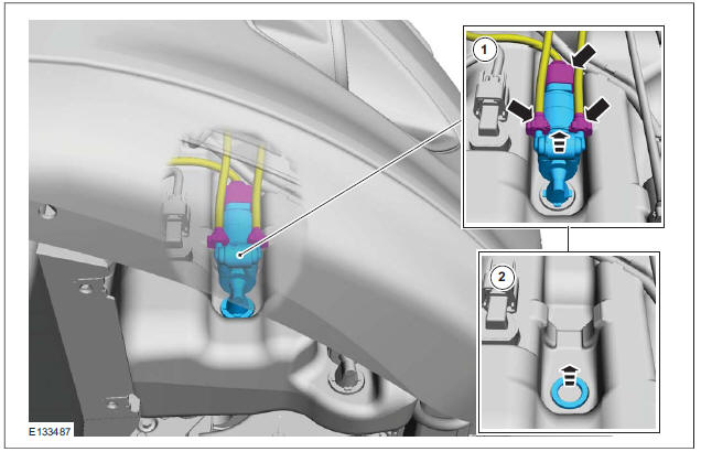
NOTE: GAS style procedures can be identified by steps that have no accompanying step text and the magenta color of the electrical connectors and fasteners such as nuts, bolts, clamps or clips.
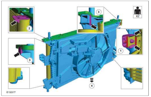
A GAS removal and installation procedure uses a sequence of color illustrations to indicate the order to be followed when removing/disassembling or installing/assembling a component.
Many of the GAS procedures will have the installation information within the removal steps.
These procedures will have the following note at the beginning of the procedure:
NOTE: Removal steps in this procedure may contain installation details.
Reuse of fasteners and seals and gaskets
The following list details the general policy for the reuse of fasteners and seals and gaskets.
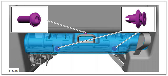
Types of self-locking nuts and bolts
NOTE: There are more types of self-locking fasteners available than shown in following illustration.
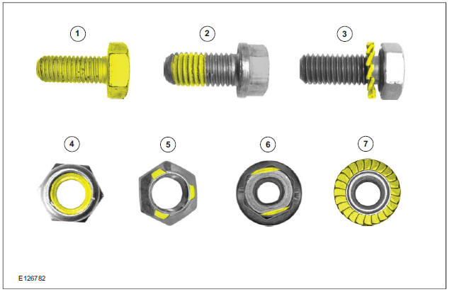
| Item | Description |
| 1 | Completely coated self-locking bolt |
| 2 | Partially coated self-locking bolt |
| 3 | Self-locking bolt with a locking washer |
| 4 | Self-locking nut with a plastic locking insert |
| 5 | Self-locking nut with thread deformation (3 identations) |
| 6 | Self-locking nut with thread deformation (to oval shape) |
| 7 | Self-locking nut with integrated locking ring |
- All types of seals and gaskets must be discarded and new seals and gaskets installed unless otherwise stated within the procedure.
- Nuts and bolts with a chemical coating for locking and/or sealing and/or antiseize must be discarded unless the procedure advises to reapply the coating with a specified material.
- Nuts and bolts with a mechanical locking such as thread inserts, thread deformation or locking washers must be discarded and new nuts and bolts installed unless otherwise stated within the procedure.
- Torque to yield bolts must be discarded and new torque to yield bolts installed unless otherwise stated within the procedure, recognizable by a tightening torque with more than one stage together with a torque angle.
Reuse of exterior trim parts
All type of glued exterior trim parts or parts fastened with adhesive tape must be discarded and new parts installed unless otherwise stated within the procedure.
Specification data
Specification procedures will only contain technical data that is not already part of a repair procedure.
Sequence of tasks
If components must be removed or installed in a specific sequence, the sequence will be identified numerically in a graphic and the corresponding text will be numbered accordingly.
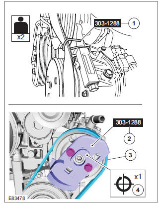
Special Tools, Equipment, Materials and Torque Figures
Special tools will be shown with the tool numbers in the illustration. The special tool numbers, general equipment, materials and torque figures used for the procedure step will be shown in the text column.
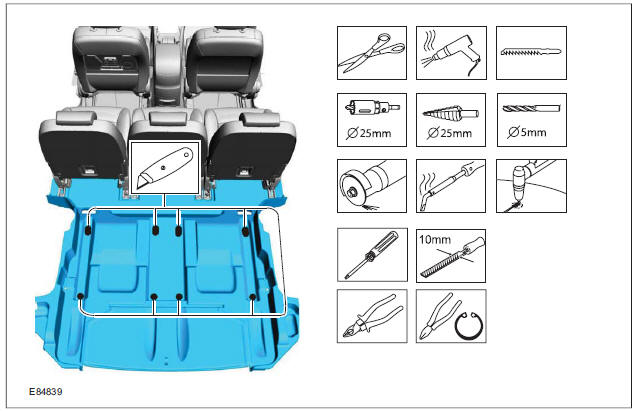
GAS Graphics
NOTE: Colors used in the graphic are as follows:
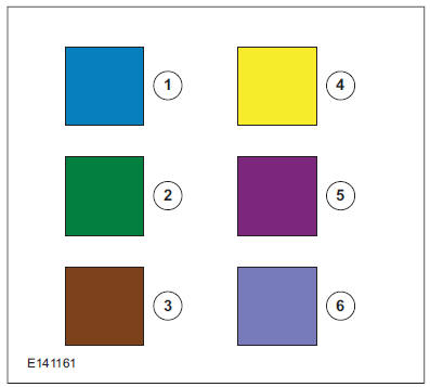
| Item | Description |
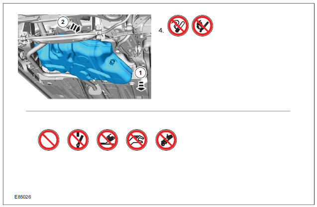
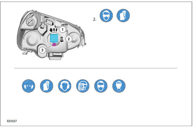
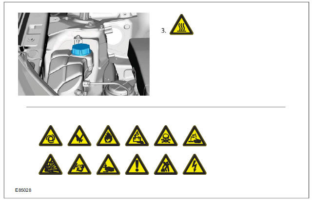
| 1 | Blue - Target or primary component to be removed/installed (or disassembled/assembled). |
| 2 | Green - Components that need to be removed prior to or installed after the target/primary. |
| 3 | Brown - Components that need to be removed prior to or installed after the target/primary. |
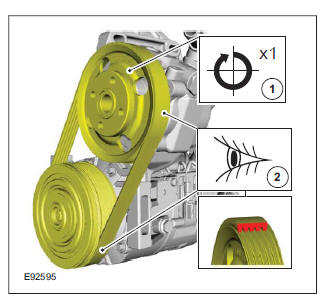
| 4 | Yellow - Components to be set aside only, that remains in the vehicle. Also highlighted areas to inspect or adjust. |
| 5 | Magenta - Electrical connectors and fasteners such as nuts, bolts, clamps, or clips to be: detached, attached, loosened, moved, removed or installed. |
| 6 | Pale Blue - Special tool(s), general equipment, or common tools (used in an uncommon way). |
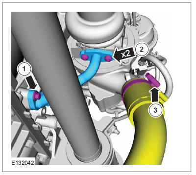
One illustration may have multiple steps assigned to it.
Numbered pointers are used to indicate the number of electrical connectors and fasteners such as nuts, bolts, clamps and clips.
Items in the illustration can be transparent or use cutouts to show hidden details.
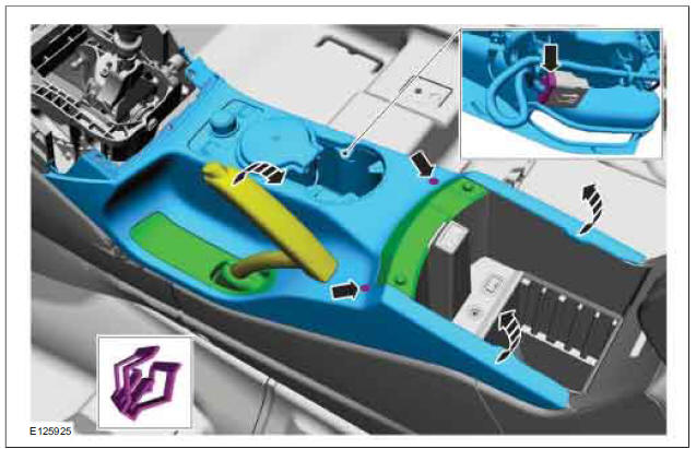
GAS Service Action Icon
Symbols are used inside the graphics and in the text area to enhance the information display. The following paragraphs describe the various types and categories of symbols.
For additional information, refer to: Symbols Glossary (100-00 General Information, Description and Operation).
Prohibition symbols advise on prohibited actions to either avoid damage or health and safety related risks. These symbols are:
Health and Safety symbols recommend the use of particular protection equipment to avoid or at least reduce the risk or severity of possible injuries.
Warning symbols are used to indicate potential risks resulting from a certain component or area.
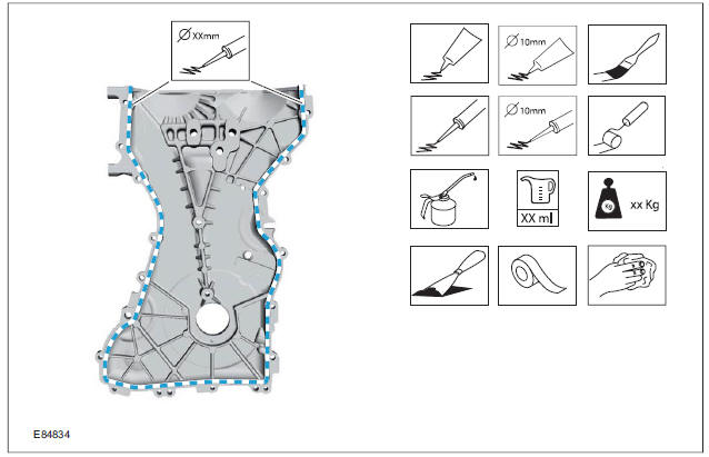
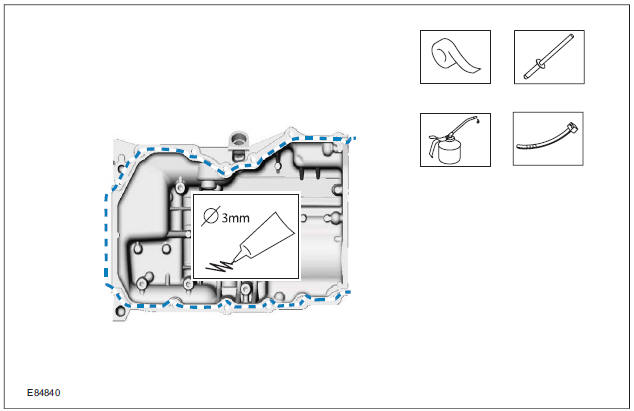
Instruction symbols are used to apply sealer, lubricant, weight, tape or cleaning detergent to a component.
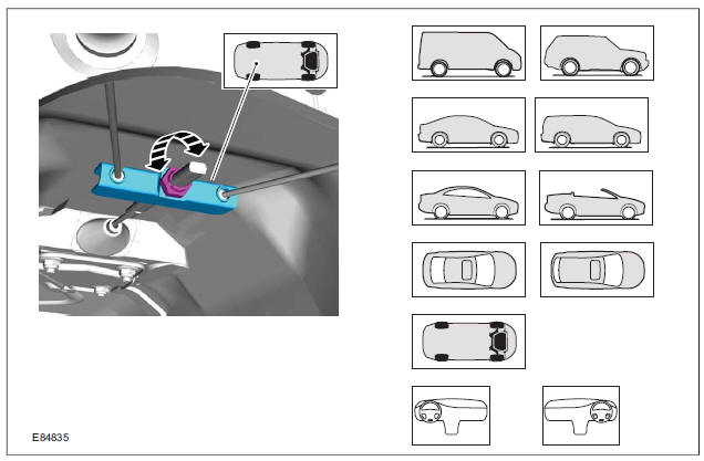
Location symbols are used to show the location of a component or system within the vehicle.
Gearshift lever or selector lever position symbols are used to show which gearshift lever or selector lever position is to be set.
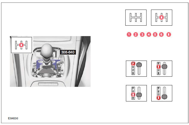
Pointer symbols are used to draw attention to components and give special instructions such as a required sequence or number of components.
The number of components is reflected by the value inside the luty arrow. A sequence number is located inside the circle. Numbers inside circles are also used to allocate special information such as tightening torques or chemicals to a particular component.
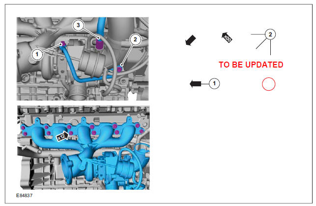
Movement arrows are used to show three dimensional or rotational movements. These movements can include specific values inside the symbol if required.
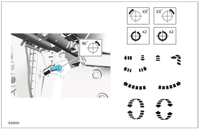
Standard tool symbols recommend the use of certain standard tools. These tools can include dimension values if required.
The following graphic illustrates a set of symbols that are used to provide detailed information on where to apply a material.
| Item | Description |
| 1 | Steering wheel in straight ahead position |
| 2 | Steering column lock locked |
| 3 | Steering column lock unlocked |
| 4 | Turn the steering wheel to the 90 left position |
| 5 | Turn the steering wheel to the 90 right position |
| 6 | Turn the steering wheel to the left-hand end position |
| 7 | Turn the steering wheel to the right-hand end position |
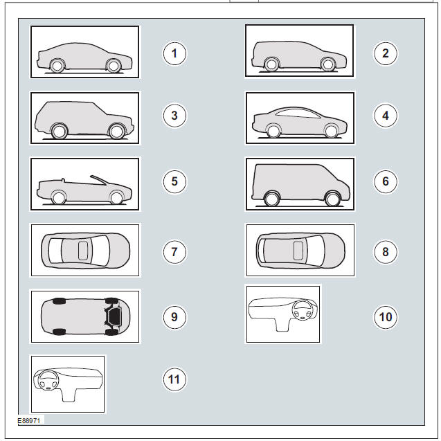
| Item | Description |
| 1 | 3, 4, 5-door body style |
| 2 | Wagon body style |
| 3 | Sports utility vehicle body style |
| 4 | Coupe body style |
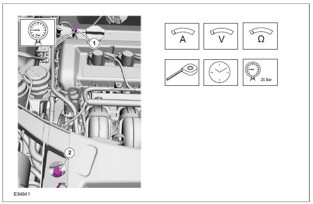
Measurement symbols provide detailed information on where to carry out a specific measurement.
These symbols can include specific values if required.
Introduction
How to use Repair Procedures
Global Authoring Standards (GAS) Repair Procedures
How to use Diagnosis and Testing procedures
Ford Kuga Service Manual
- General Information
- Jacking and Lifting
- Noise, Vibration and Harshness
- Suspension System - General Information
- Climate Control
- Auxiliary Climate Control
- Instrument Cluster and Panel Illumination
- Instrument Cluster
- Horn
- Warning Devices
- Parking Aid
- Charging System - General Information
- Battery, Mounting and Cables
- Generator and Regulator
- Voltage Converter/Inverter
- Information and Entertainment System - General Information
- Information and Entertainment System
- Exterior Lighting
- Interior Lighting
- Daytime Running Lamps (DRL)
- Module Communications Network
- Module Configuration
- Wiring Harnesses
- Anti-Theft - Active
- Anti-Theft - Passive
- Multifunction Electronic Modules
- Front End Body Panels
- Body Closures
- Interior Trim and Ornamentation
- Exterior Trim and Ornamentation
- Rear View Mirrors
- Seating
- Glass, Frames and Mechanisms
- Instrument Panel and Console
- Handles, Locks, Latches and Entry Systems
- Wipers and Washers
- Bumpers
- Safety Belt System
- Supplemental Restraint System
- Body Repairs - General Information
- Body Repairs - Vehicle Specific Information and Tolerance Checks
- Front End Sheet Metal Repairs
- Roof Sheet Metal Repairs
- Side Panel Sheet Metal Repairs
- Rear End Sheet Metal Repairs
- Paint - General Information
- Uni-Body, Subframe and Mounting System
- Suspension System - General Information
- Front Suspension
- Rear Suspension
- Wheels and Tires
- Driveshaft
- Rear Drive Axle/Differential
- Front Drive Halfshafts
- Rear Drive Halfshafts
- Brake System - General Information
- Front Disc Brake
- Rear Disc Brake
- Parking Brake and Actuation
- Hydraulic Brake Actuation
- Power Brake Actuation
- Anti-Lock Control
- Anti-Lock Control - Stability Assist
- Steering System - General Information
- Power Steering
- Steering Linkage
- Steering Column
- Steering Column Switches
- Engine System - General Information
- Engine- 2.5L Duratec (147kW/200PS) - VI5
- Engine Cooling
- Fuel Charging and Controls-2.5L Duratec (147kW/200PS) - VI5
- Fuel Charging and Controls - Turbocharger- 2.5L Duratec (147kW/200PS) - VI5
- Accessory Drive - 2.5L Duratec (147kW/200PS) - VI5
- Starting System- 2.5L Duratec (147kW/200PS) - VI5
- Engine Ignition - 2.5L Duratec (147kW/200PS) - VI5
- Engine Emission Control - 2.5L Duratec (147kW/200PS) - VI5
- Intake Air Distribution and Filtering - 2.5L Duratec (147kW/200PS) - VI5
- Evaporative Emissions
- Electronic Engine Controls
- Automatic Transmission/Transaxle
- Transmission/Transaxle Cooling
- Automatic Transmission/Transaxle External Controls
- Transfer Case
- Exhaust System-
- Fuel System
- Fuel Tank and Lines
- Acceleration Control
- Speed Control
- Climate Control System
- Climate Control
Main Categories

0.0078