 Ford Kuga Service ManualParking Aid » Parking Aid - Vehicles With: Rear Parking Aid
Pinpoint Tests
Pinpoint Tests
| TEST CONDITIONS | DETAILS/RESULTS/ACTIONS |
| PINPOINT TEST H : THE REAR PARKING AID IS INOPERATIVE/DOES NOT OPERATE CORRECTLY | |
| A1: CHECK FOR VOLTAGE TO THE PARKING AID MODULE | |
 |
Yes GO to A2. No REPAIR the circuit 15-GN10 (GN/YE). TEST the system for normal operation. |
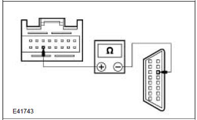
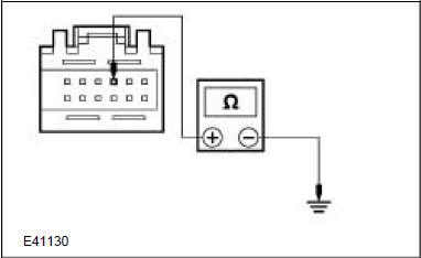
| A2: CHECK THE PARKING AID MODULE GROUND CIRCUIT | |
 |
Is the resistance less than 5 Ohms? Yes GO to A3. No REPAIR the circuit 31-GN10 (BK/YE). TEST the system for normal operation. |
| A3: CHECK THE REVERSE LAMP FOR CORRECT OPERATION | |
Yes GO to A4. No REFER to: Reversing Lamps (417-01 Exterior Lighting, Diagnosis and Testing). TEST the system for normal operation. |
|
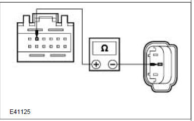
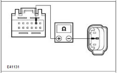
| A4: CHECK THE REAR PARKING AID SPEAKER FOR CORRECT OPERATION | |
 |
Yes GO to A5. No INSTALL a new rear parking aid speaker. TEST the system for normal operation. |
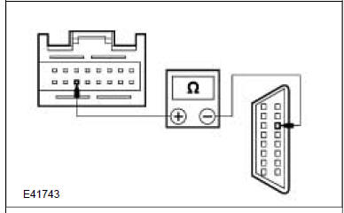
| A5: CHECK THE CIRCUIT 8-GN26 FOR OPEN | |
 |
Yes GO to A6. No REPAIR the circuit. TEST the system for normal operation. |
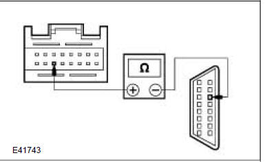
| A6: CHECK THE CIRCUIT 10-GN26 FOR OPEN | |
 |
Yes For vehicles fitted with a rear trailer tow module. GO to Pinpoint Test J. For vehicles fitted without a rear trailer tow module. INSTALL a new parking aid module. REFER to: Parking Aid Module (413-13 Parking Aid, Removal and Installation). TEST the system for normal operation. No REPAIR the circuit. TEST the system for normal operation. |
| PINPOINT TEST I : NO COMMUNICATION WITH THE PARKING AID MODULE | |
| B1: CHECK THAT THE FORD DIAGNOSTIC EQUIPMENT IS COMMUNICATING THROUGH THE DLC | |
Is the Ford diagnostic equipment able to communicate with the selected system. Yes GO to B2. No CHECK the DLC. For additional information, refer to the Wiring Diagrams. |
|
| B2: CHECK THE CIRCUIT 8-EE13 FOR OPEN | |
 |
Yes GO to B3. No REPAIR the circuit 8-EE13 (WH/RD). TEST the system for normal operation.
|
| B2: CHECK THE CIRCUIT 8-EE13 FOR OPEN | |
 |
Yes GO to B3. No REPAIR the circuit 8-EE13 (WH/RD). TEST the system for normal operation. |
| B3: CHECK THE DLC CIRCUIT FOR OPEN | |
 |
Yes INSTALL a new parking aid module. REFER to: Parking Aid Module (413-13 Parking Aid, Removal and Installation). TEST the system for normal operation. No REPAIR the circuit. TEST the system for normal operation. |
| PINPOINT TEST I : NO COMMUNICATION WITH THE PARKING AID MODULE | |
| B1: CHECK THAT THE FORD DIAGNOSTIC EQUIPMENT IS COMMUNICATING THROUGH THE DLC | |
Yes GO to B2. No CHECK the DLC. For additional information, refer to the Wiring Diagrams. |
|
| B2: CHECK THE CIRCUIT 8-EE13 FOR OPEN | |
 |
Yes GO to B3. No REPAIR the circuit 8-EE13 (WH/RD). TEST the system for normal operation. |
| B3: CHECK THE DLC CIRCUIT FOR OPEN | |
 |
Yes INSTALL a new parking aid module. REFER to: Parking Aid Module (413-13 Parking Aid, Removal and Installation). TEST the system for normal operation. No REPAIR the circuit. TEST the system for normal operation. |
| PINPOINT TEST J : DTC C1700 : REAR OUTER LEFT SENSOR SIGNAL CIRCUIT OPEN OR SHORT TO GROUND | |
| C1: CHECK CIRCUIT 8-GN22 (WH/GN) FOR OPEN | |
 |
Yes GO to C2. No REPAIR the circuit. TEST the system for normal operation |
| C2: CHECK CIRCUIT 8-GN22 (WH/GN) FOR SHORT TO GROUND | |
 |
Is the resistance greater than 10,000 Ohms? Yes INSTALL a new parking aid sensor. If the concern persists, INSTALL a new parking aid module. REFER to: Parking Aid Module (413-13 Parking Aid, Removal and Installation). No REPAIR the short to ground. TEST the system for normal operation. |
| PINPOINT TEST K: DTC C1703 : REAR OUTER RIGHT SENSOR SIGNAL CIRCUIT OPEN OR SHORT TO GROUND | |
| D1: CHECK CIRCUIT 8-GN19 (WH) FOR OPEN | |
 |
Yes GO to D2. No REPAIR the circuit. TEST the system for normal operation. |
| D2: CHECK CIRCUIT 8-GN19 (WH) FOR SHORT TO GROUND | |
 |
Yes INSTALL a new parking aid sensor. If the concern persists, INSTALL a new parking aid module. REFER to: Parking Aid Module (413-13 Parking Aid, Removal and Installation). No REPAIR the short to ground. TEST the system for normal operation. |
| PINPOINT TEST L : DTC C1706 : REAR INNER LEFT SENSOR SIGNAL CIRCUIT OPEN OR SHORT TO GROUND | |
| E1: CHECK CIRCUIT 8-GN21 (WH/BU) FOR OPEN | |
 |
Yes GO to E2. No REPAIR the circuit. TEST the system for normal operation. |
| E2: CHECK CIRCUIT 8-GN21 (WH/BU) FOR SHORT TO GROUND | |
 |
Yes INSTALL a new parking aid sensor. If the concern persists, INSTALL a new parking aid module. REFER to: Parking Aid Module (413-13 Parking Aid, Removal and Installation). No REPAIR the short to ground. TEST the system for normal operation. |
| PINPOINT TEST M : DTC C1709 : REAR INNER RIGHT SENSOR SIGNAL CIRCUIT OPEN OR SHORT TO GROUND | |
| F1: CHECK CIRCUIT 8-GN20 (WH/RD) FOR OPEN | |
 |
Yes GO to F2. No REPAIR the circuit. TEST the system for normal operation. |
| F2: CHECK CIRCUIT 8-GN20 (WH/RD) FOR SHORT TO GROUND | |
 |
Yes INSTALL a new parking aid sensor. If the concern persists, INSTALL a new parking aid module. REFER to: Parking Aid Module (413-13 Parking Aid, Removal and Installation). No REPAIR the short to ground. TEST the system for normal operation. |
| PINPOINT TEST N : DTCB1299 : PARKING AID SENSOR VOLTAGE SUPPLY SHORT TO GROUND | |
| G1: CHECK THE CIRCUIT 7-GN19 (YE/RD) FOR SHORT TO GROUND | |
 |
Is the resistance greater than 10,000 Ohms? Yes GO to G2. No REPAIR the short to ground. TEST the system for normal operation. |
| G2: CHECK EACH PARKING AID SENSOR FOR SHORT BETWEEN PINS 1 AND 3 | |
 |
Yes INSTALL a new parking aid sensor(s). TEST the system for normal operation. No INSTALL a new parking aid module. TEST the system for normal operation. |
| PINPOINT TEST O : DTC C1742 PARKING AID SPEAKER CIRCUIT SHORT TO GROUND | |
| H1: CHECK THE REAR PARKING AID SPEAKER FOR CORRECT OPERATION | |
 |
Yes GO to H2. No INSTALL a new rear parking aid speaker. TEST the system for normal operation. |
| H2: CHECK THE CIRCUIT 8-GN26 (WH) FOR SHORT TO GROUND | |
 |
Yes INSTALL a new rear parking aid speaker. TEST the system for normal operation. If the concern persists, INSTALL a new parking aid module. REFER to: Parking Aid Module (413-13 Parking Aid, Removal and Installation). TEST the system for normal operation. No GO to H3. |
| H3: CHECK THE CIRCUIT 10-GN26 (GY) FOR SHORT TO GROUND | |
 |
Yes For vehicles fitted with a rear trailer tow module. GO to Pinpoint Test J. For vehicles fitted without a rear trailer tow module. INSTALL a new parking aid module. REFER to: Parking Aid Module (413-13 Parking Aid, Removal and Installation). TEST the system for normal operation. No REPAIR the short to ground. TEST the system for normal operation. |
| PINPOINT TEST P : DTC C1743 PARKING AID SPEAKER CIRCUIT SHORT TO BATTERY | |
| 11: CHECK THE REAR PARKING AID SPEAKER FOR CORRECT OPERATION | |
 |
Yes GO to 12. No INSTALL a new rear parking aid speaker. TEST the system for normal operation. |
| 12: CHECK THE CIRCUIT 8-GN26 (WH) FOR OPEN | |
 |
Yes GO to 13. No REPAIR the circuit. TEST the system for normal operation. |
| 13: CHECK THE CIRCUIT 10-GN26 (GY) FOR OPEN | |
 |
Yes For vehicles fitted with a rear trailer tow module. GO to Pinpoint Test J. For vehicles fitted without a rear trailer tow module. INSTALL a new parking aid module. REFER to: Parking Aid Module (413-13 Parking Aid, Removal and Installation). TEST the system for normal operation. No REPAIR the circuit. TEST the system for normal operation. |
| PINPOINT TEST Q : THE PARKING AID SYSTEM DOES NOT DEACTIVATE WHEN A TRAILER IS ATTACHED | |
| J1: CHECK PARKING AID MODULE CIRCUIT 9-GN18 (BN/BU) FOR SHORT TO GROUND | |
 |
Yes TEST the system for normal operation. No REPAIR the short to ground. TEST the system for normal operation. |
Principles of Operation
Inspection and Verification
Diagnostic Trouble Codes (DTC) Index
Pinpoint Tests
Ford Kuga Service Manual
- General Information
- Jacking and Lifting
- Noise, Vibration and Harshness
- Suspension System - General Information
- Climate Control
- Auxiliary Climate Control
- Instrument Cluster and Panel Illumination
- Instrument Cluster
- Horn
- Warning Devices
- Parking Aid
- Charging System - General Information
- Battery, Mounting and Cables
- Generator and Regulator
- Voltage Converter/Inverter
- Information and Entertainment System - General Information
- Information and Entertainment System
- Exterior Lighting
- Interior Lighting
- Daytime Running Lamps (DRL)
- Module Communications Network
- Module Configuration
- Wiring Harnesses
- Anti-Theft - Active
- Anti-Theft - Passive
- Multifunction Electronic Modules
- Front End Body Panels
- Body Closures
- Interior Trim and Ornamentation
- Exterior Trim and Ornamentation
- Rear View Mirrors
- Seating
- Glass, Frames and Mechanisms
- Instrument Panel and Console
- Handles, Locks, Latches and Entry Systems
- Wipers and Washers
- Bumpers
- Safety Belt System
- Supplemental Restraint System
- Body Repairs - General Information
- Body Repairs - Vehicle Specific Information and Tolerance Checks
- Front End Sheet Metal Repairs
- Roof Sheet Metal Repairs
- Side Panel Sheet Metal Repairs
- Rear End Sheet Metal Repairs
- Paint - General Information
- Uni-Body, Subframe and Mounting System
- Suspension System - General Information
- Front Suspension
- Rear Suspension
- Wheels and Tires
- Driveshaft
- Rear Drive Axle/Differential
- Front Drive Halfshafts
- Rear Drive Halfshafts
- Brake System - General Information
- Front Disc Brake
- Rear Disc Brake
- Parking Brake and Actuation
- Hydraulic Brake Actuation
- Power Brake Actuation
- Anti-Lock Control
- Anti-Lock Control - Stability Assist
- Steering System - General Information
- Power Steering
- Steering Linkage
- Steering Column
- Steering Column Switches
- Engine System - General Information
- Engine- 2.5L Duratec (147kW/200PS) - VI5
- Engine Cooling
- Fuel Charging and Controls-2.5L Duratec (147kW/200PS) - VI5
- Fuel Charging and Controls - Turbocharger- 2.5L Duratec (147kW/200PS) - VI5
- Accessory Drive - 2.5L Duratec (147kW/200PS) - VI5
- Starting System- 2.5L Duratec (147kW/200PS) - VI5
- Engine Ignition - 2.5L Duratec (147kW/200PS) - VI5
- Engine Emission Control - 2.5L Duratec (147kW/200PS) - VI5
- Intake Air Distribution and Filtering - 2.5L Duratec (147kW/200PS) - VI5
- Evaporative Emissions
- Electronic Engine Controls
- Automatic Transmission/Transaxle
- Transmission/Transaxle Cooling
- Automatic Transmission/Transaxle External Controls
- Transfer Case
- Exhaust System-
- Fuel System
- Fuel Tank and Lines
- Acceleration Control
- Speed Control
- Climate Control System
- Climate Control
Main Categories

0.0166