 Ford Kuga Service ManualMultifunction Electronic Modules » Module Controlled Functions (System Operation and Component Description)
System Diagram
Ford Kuga
Service Manual
System Diagram
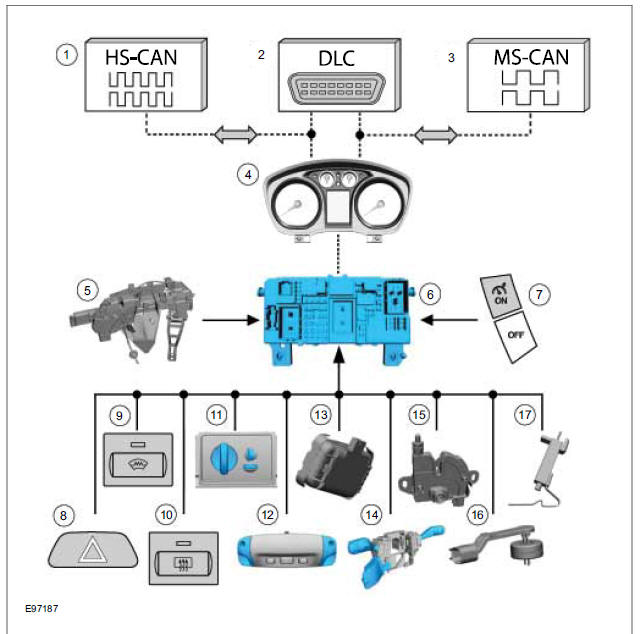
Generic Electronic Module (GEM) input signals
|
Item |
Description |
| 1 | High speed CAN (controller area network) bus (HS-CAN) |
| 2 | DLC (data link connector) |
| 3 | Medium speed CAN bus (MS-CAN) |
| 4 | Instrument cluster (gateway) |
| 5 | Door contact switch |
| 6 | GEM |
| 7 | Speed control switch |
| 8 | Hazard flasher switch |
| 9 | Windscreen heater switch |
| 10 | Rear window heater switch |
| 11 | Light switch |
| 12 | Interior scanning sensors - anti-theft alarm system |
| 13 | Light/rain sensor |
| 14 | Multifunction switch |
| 15 | Hood switch |
| 16 | Brake fluid level switch |
| 17 | Outside air temperature sensor |
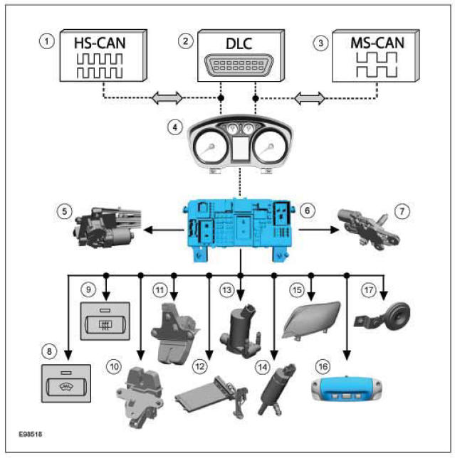
GEM output signals
| Item | Description |
| 1 | HS CAN |
| 2 | DLC |
| 3 | MS CAN |
| 4 | Instrument cluster (gateway) |
| 5 | Front windshield wiper motors |
| 6 | GEM |
| 7 | Rear window wiper motors |
| 8 | Indicator/heated windshield |
| 9 | Indicator/heated rear window |
| 10 | Mini-liftgate latch motor |
| 11 | Liftgate latch motor |
| 12 | Electric booster Heater |
| 13 | Front wiper windscreen washer pump |
| 14 | Rear wiper windscreen washer pump |
| 15 | Headlamp |
| 16 | Courtesy Lighting |
| 17 | Alarm horn |
More about «Module Controlled Functions (System Operation and Component Description)»:
System Diagram
System Operation
Ford Kuga Service Manual
- General Information
- Jacking and Lifting
- Noise, Vibration and Harshness
- Suspension System - General Information
- Climate Control
- Auxiliary Climate Control
- Instrument Cluster and Panel Illumination
- Instrument Cluster
- Horn
- Warning Devices
- Parking Aid
- Charging System - General Information
- Battery, Mounting and Cables
- Generator and Regulator
- Voltage Converter/Inverter
- Information and Entertainment System - General Information
- Information and Entertainment System
- Exterior Lighting
- Interior Lighting
- Daytime Running Lamps (DRL)
- Module Communications Network
- Module Configuration
- Wiring Harnesses
- Anti-Theft - Active
- Anti-Theft - Passive
- Multifunction Electronic Modules
- Front End Body Panels
- Body Closures
- Interior Trim and Ornamentation
- Exterior Trim and Ornamentation
- Rear View Mirrors
- Seating
- Glass, Frames and Mechanisms
- Instrument Panel and Console
- Handles, Locks, Latches and Entry Systems
- Wipers and Washers
- Bumpers
- Safety Belt System
- Supplemental Restraint System
- Body Repairs - General Information
- Body Repairs - Vehicle Specific Information and Tolerance Checks
- Front End Sheet Metal Repairs
- Roof Sheet Metal Repairs
- Side Panel Sheet Metal Repairs
- Rear End Sheet Metal Repairs
- Paint - General Information
- Uni-Body, Subframe and Mounting System
- Suspension System - General Information
- Front Suspension
- Rear Suspension
- Wheels and Tires
- Driveshaft
- Rear Drive Axle/Differential
- Front Drive Halfshafts
- Rear Drive Halfshafts
- Brake System - General Information
- Front Disc Brake
- Rear Disc Brake
- Parking Brake and Actuation
- Hydraulic Brake Actuation
- Power Brake Actuation
- Anti-Lock Control
- Anti-Lock Control - Stability Assist
- Steering System - General Information
- Power Steering
- Steering Linkage
- Steering Column
- Steering Column Switches
- Engine System - General Information
- Engine- 2.5L Duratec (147kW/200PS) - VI5
- Engine Cooling
- Fuel Charging and Controls-2.5L Duratec (147kW/200PS) - VI5
- Fuel Charging and Controls - Turbocharger- 2.5L Duratec (147kW/200PS) - VI5
- Accessory Drive - 2.5L Duratec (147kW/200PS) - VI5
- Starting System- 2.5L Duratec (147kW/200PS) - VI5
- Engine Ignition - 2.5L Duratec (147kW/200PS) - VI5
- Engine Emission Control - 2.5L Duratec (147kW/200PS) - VI5
- Intake Air Distribution and Filtering - 2.5L Duratec (147kW/200PS) - VI5
- Evaporative Emissions
- Electronic Engine Controls
- Automatic Transmission/Transaxle
- Transmission/Transaxle Cooling
- Automatic Transmission/Transaxle External Controls
- Transfer Case
- Exhaust System-
- Fuel System
- Fuel Tank and Lines
- Acceleration Control
- Speed Control
- Climate Control System
- Climate Control
Main Categories

© 2017-2026 Copyright www.fokuman.com
0.0154
0.0154