 Ford Kuga Service ManualClimate Control » Climate Control (System Operation and Component Description)
System Operation
System Operation
Climate control housing
General overview
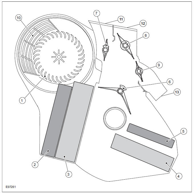
| Item | Description |
| 1 | Blower motor Refer to Component Description |
| 2 | Pollen filter Refer to Component Description |
| 3 | Evaporator assembly |
| 4 | Heat exchanger |
| 5 | Electric booster heater (if equipped) |
| 6 | Temperature blend door motor |
| 7 | Air distribution flap, demister vents |
| 8 | Air distribution door - center vents |
| 9 | Air distribution door - footwell |
| 10 | Air intake door |
| 11 | Air duct, demister vents |
| 12 | Air passages - center vents |
| 13 | Air ducts, rear footwell |
Air flow - defroster vents
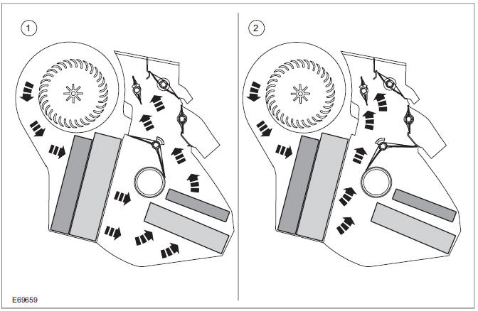
| Item | Description |
| 1 | Warm air |
| 2 | Cold air |
Air flow - center vents
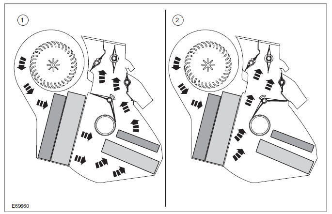
| Item | Description |
| 1 | Warm air |
| 2 | Cold air |
Air flow - footwell
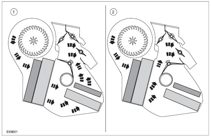
| Item | Description |
| 1 | Warm air |
| 2 | Cold air |
Climate control
Two options are available:
- manual climate control
- Air conditioning system with automatic temperature control (DEATC)
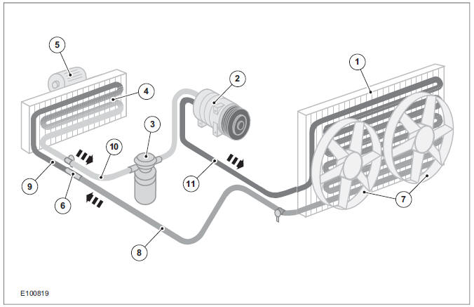
| Item | Description |
| 1 | Condenser |
| 2 | Air conditioning compressor |
| 3 | Suction accumulator |
| 4 | Evaporator assembly |
| 5 | Blower motor |
| 6 | Evaporator Core Orifice Tube |
| 7 | Cooling fans |
| 8 | High - pressure (liquid and warm) |
| 9 | Low - pressure (liquid and cool) |
| 10 | Low pressure (gaseous and cold) |
| 11 | High pressure (gaseous and hot) |
The engine driven refrigerant compressor (2) sucks in gaseous refrigerant from the suction accumulator and compresses it. The temperature of the refrigerant rises to a value between 70 C and 110 C. It passes to the condenser (1) under high pressure.
At this point heat is drawn from the refrigerant by the air being forced past the cooling fins. Because of this heat loss, the refrigerant liquefies and leaves the condenser.
A fixed orifice tube (6), which separates the refrigerant at high pressure from that at low pressure, is located between the condenser and the evaporator (5). This fixed orifice tube slows down the flow of the refrigerant from the compressor, so that pressure builds up in the condenser.
After passing through the fixed orifice tube the liquid refrigerant expands in the circuit to the evaporator, where it becomes gaseous. This causes heat to be extracted from the air coming into the vehicle. The air cools down, and excess moisture contained in it is condensed and is drained off. The refrigerant coming from the evaporator flows into the refrigerant accumulator and is again sucked in by the refrigerant compressor.
The system is protected by a high-pressure limiting switch, in order to prevent damage by excessive pressure (e.g. because of overfilling with refrigerant). If the pressure exceeds the maximum permitted, the high-pressure switch turns off the refrigerant compressor.
The compressor on-off cycle is controlled by the dual pressure switch depending on the pressure in the refrigerant accumulator. The dual pressure switch turns the refrigerant compressor off permanently if the pressure falls below a permitted value (e.g. if there is a leak).
System Diagram
System Operation
Component Description
Air Conditioning (A/C) Compressor - 2.5L Duratec (147kW/200PS) - VI5(34 626 4)
Air Conditioning (A/C) Compressor to Condenser Discharge Line
Air Conditioning (A/C) Compressor to Condenser Discharge Line - 2.5L Duratec (147kW/200PS) - VI5
Ford Kuga Service Manual
- General Information
- Jacking and Lifting
- Noise, Vibration and Harshness
- Suspension System - General Information
- Climate Control
- Auxiliary Climate Control
- Instrument Cluster and Panel Illumination
- Instrument Cluster
- Horn
- Warning Devices
- Parking Aid
- Charging System - General Information
- Battery, Mounting and Cables
- Generator and Regulator
- Voltage Converter/Inverter
- Information and Entertainment System - General Information
- Information and Entertainment System
- Exterior Lighting
- Interior Lighting
- Daytime Running Lamps (DRL)
- Module Communications Network
- Module Configuration
- Wiring Harnesses
- Anti-Theft - Active
- Anti-Theft - Passive
- Multifunction Electronic Modules
- Front End Body Panels
- Body Closures
- Interior Trim and Ornamentation
- Exterior Trim and Ornamentation
- Rear View Mirrors
- Seating
- Glass, Frames and Mechanisms
- Instrument Panel and Console
- Handles, Locks, Latches and Entry Systems
- Wipers and Washers
- Bumpers
- Safety Belt System
- Supplemental Restraint System
- Body Repairs - General Information
- Body Repairs - Vehicle Specific Information and Tolerance Checks
- Front End Sheet Metal Repairs
- Roof Sheet Metal Repairs
- Side Panel Sheet Metal Repairs
- Rear End Sheet Metal Repairs
- Paint - General Information
- Uni-Body, Subframe and Mounting System
- Suspension System - General Information
- Front Suspension
- Rear Suspension
- Wheels and Tires
- Driveshaft
- Rear Drive Axle/Differential
- Front Drive Halfshafts
- Rear Drive Halfshafts
- Brake System - General Information
- Front Disc Brake
- Rear Disc Brake
- Parking Brake and Actuation
- Hydraulic Brake Actuation
- Power Brake Actuation
- Anti-Lock Control
- Anti-Lock Control - Stability Assist
- Steering System - General Information
- Power Steering
- Steering Linkage
- Steering Column
- Steering Column Switches
- Engine System - General Information
- Engine- 2.5L Duratec (147kW/200PS) - VI5
- Engine Cooling
- Fuel Charging and Controls-2.5L Duratec (147kW/200PS) - VI5
- Fuel Charging and Controls - Turbocharger- 2.5L Duratec (147kW/200PS) - VI5
- Accessory Drive - 2.5L Duratec (147kW/200PS) - VI5
- Starting System- 2.5L Duratec (147kW/200PS) - VI5
- Engine Ignition - 2.5L Duratec (147kW/200PS) - VI5
- Engine Emission Control - 2.5L Duratec (147kW/200PS) - VI5
- Intake Air Distribution and Filtering - 2.5L Duratec (147kW/200PS) - VI5
- Evaporative Emissions
- Electronic Engine Controls
- Automatic Transmission/Transaxle
- Transmission/Transaxle Cooling
- Automatic Transmission/Transaxle External Controls
- Transfer Case
- Exhaust System-
- Fuel System
- Fuel Tank and Lines
- Acceleration Control
- Speed Control
- Climate Control System
- Climate Control
Main Categories

0.0163