 Ford Kuga Service ManualAnti-Lock Control - Stability Assist » Anti-Lock Control - Stability Assist (System Operation and Component
Description)
Ford Kuga Service ManualAnti-Lock Control - Stability Assist » Anti-Lock Control - Stability Assist (System Operation and Component
Description)
Component Description
Component Description
Opto-electronic steering wheel rotation sensor
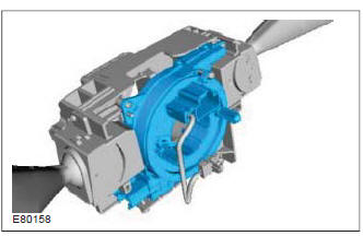
The opto-electronic steering wheel rotation sensors use light barriers for contactless scanning of a segment disk which is connected fixedly to the steering shaft.
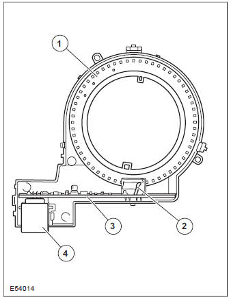
| Item | Description |
| 1 | Segment disk |
| 2 | Photoelectric barrier |
| 3 | Electronics |
| 4 | Electrical connection |
Use is made of opto-electronic types of sensors with relative and absolute steering angle sensing.
For relative steering angle sensing, changes in the steering angle are measured exclusively by the sensor and transmitted to the ABS/ESP module.
With the aid of other vehicle status signals (e.g.
wheel speed sensors) the module calculates the straight ahead position of the steering. For absolute steering angle sensing, the sensor transmits a specific signal to the module for each steering angle position (in relation to one turn of the steering wheel). The straight ahead position of the steering is therefore defined in the sensor. On an absolute steering angle sensor, several photoelectric barrier modules are distributed around the segment disk at varying distances. The gaps between segments of the segment disk are also unequal. For each specific steering angle there is therefore a specific switch status of all photoelectric barriers.
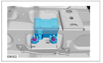
ABS/ESP module or hydraulic control unit (HCU)
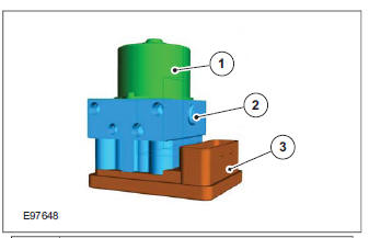
| Item | Description |
| 1 | ABS Pump Motor |
| 2 | Valve block (with low-pressure accumulators) |
| 3 | ABS module |
The HCU comprises the ABS module, the valve block (with low-pressure accumulators) and the ABS pump.
The valve block combines all of the brake pressure control valves in one unit. Depending on the system, either simple changeover valves or proportioning valves (e.g. on EBD (electronic brake force distribution) systems) are installed. The low-pressure accumulators store the brake fluid that is returned from the wheel brakes during the pressure reduction phase until it is drawn back into the system by the ABS pump.
The ABS pump is designed as a dual piston pump.
This means that two separate pump elements assure an increase in brake pressure during control interventions. A direct current motor drives the pump pistons via an eccentric shaft.
The ABS/ESP module monitors the input signals of all sensors and actuates the electro-magnetic brake pressure valves and the ABS pump as required. For reasons of safety, the module is of the redundant type, whereby processing of the signals is carried out via two separate processors that also monitor each other.
ESP switch
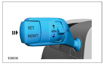
Stability assist can be deactivated via the menu in the instrument cluster. The stability assist functions are deactivated when the Set switch is actuated.
The ABS control module makes the stability assist functions available once more when the Set switch is actuated again. The stability assist function is automatically reactivated when the ignition is switched on.
The electronic EBA is a constant function and will remain active even if the ESP has been switched off.
Combined yaw rate sensor and lateral acceleration sensor / longitudinal acceleration sensor
The heart of the combined yaw rate sensor and lateral acceleration sensor/longitudinal acceleration sensor is a small, double-sided tuning fork made of a piezo crystal (A). The exciter side of this tuning fork is set to a resonance of 11 kHz with the aid of an alternating current. The measuring side of the tuning fork features a resonance frequency of 11.33 kHz and therefore does not vibrate (B). Since, under influence of an external accelerating force, a vibrating mass reacts slower than a comparable mass that is not vibrating, the tuning fork twists within itself with rotational movement being imparted on the sensor (C). This rotation results in a change in the charge distribution in the Piezo element, which is subsequently picked up and converted into an electronic signal by electronics integrated into the sensor. This electronic signal is then sent to the ESP module. The ESP module evaluates these data and takes into account the other input data (vehicle speed, wheel speed) before deciding whether the ESP function is required.
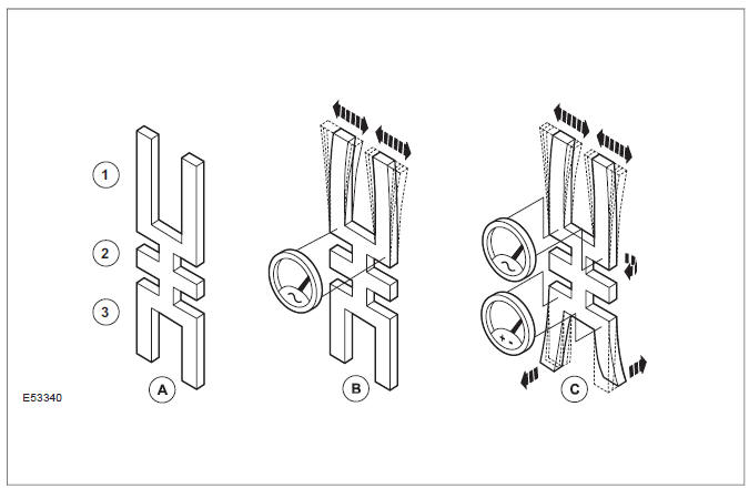
| Item | Description |
| 1 | Tuning fork exciter |
| 2 | Suspension |
| 3 | Measuring side |
Due to the special way in which it works. the combined yaw rate sensor and lateral acceleration sensor/longitudinal acceleration sensor must be installed the right way up in the designated location specified by the manufacturer. Any slight deviation in the installation position and/or installation location could lead to impaired functionality and thereby possible failure of the stability assist.
Front wheel sensor
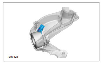
Active sensors are used to determine the rotational speeds of the wheels at the hub. After the ignition is switched on, the ABS module supplies the sensors with power. The sensors work in accordance with the Hall effect principle and generate a square wave output signal. The signal acts in proportion to the rotational speed of the sensor ring. The ABS sensor rings are built into the seals in the front wheel bearings. The ABS module evaluates the signals from all four sensors to calculate a vehicle speed signal based on the rotational speeds of all wheels. The road speed is transmitted on the CAN bus. The powertrain control module (PCM) uses this signal and the programmed tire size to calculate the vehicle speed. The calculated vehicle speed is forwarded on the CAN bus and is requested by other control units that need this input information.
Rear wheel sensor
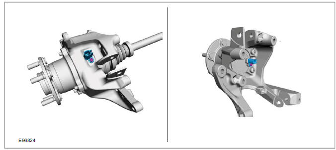
The sensors are joined to the main wiring harness using a separate connecting cable.
System Diagram
System Operation
Component Description
Ford Kuga Service Manual
- General Information
- Jacking and Lifting
- Noise, Vibration and Harshness
- Suspension System - General Information
- Climate Control
- Auxiliary Climate Control
- Instrument Cluster and Panel Illumination
- Instrument Cluster
- Horn
- Warning Devices
- Parking Aid
- Charging System - General Information
- Battery, Mounting and Cables
- Generator and Regulator
- Voltage Converter/Inverter
- Information and Entertainment System - General Information
- Information and Entertainment System
- Exterior Lighting
- Interior Lighting
- Daytime Running Lamps (DRL)
- Module Communications Network
- Module Configuration
- Wiring Harnesses
- Anti-Theft - Active
- Anti-Theft - Passive
- Multifunction Electronic Modules
- Front End Body Panels
- Body Closures
- Interior Trim and Ornamentation
- Exterior Trim and Ornamentation
- Rear View Mirrors
- Seating
- Glass, Frames and Mechanisms
- Instrument Panel and Console
- Handles, Locks, Latches and Entry Systems
- Wipers and Washers
- Bumpers
- Safety Belt System
- Supplemental Restraint System
- Body Repairs - General Information
- Body Repairs - Vehicle Specific Information and Tolerance Checks
- Front End Sheet Metal Repairs
- Roof Sheet Metal Repairs
- Side Panel Sheet Metal Repairs
- Rear End Sheet Metal Repairs
- Paint - General Information
- Uni-Body, Subframe and Mounting System
- Suspension System - General Information
- Front Suspension
- Rear Suspension
- Wheels and Tires
- Driveshaft
- Rear Drive Axle/Differential
- Front Drive Halfshafts
- Rear Drive Halfshafts
- Brake System - General Information
- Front Disc Brake
- Rear Disc Brake
- Parking Brake and Actuation
- Hydraulic Brake Actuation
- Power Brake Actuation
- Anti-Lock Control
- Anti-Lock Control - Stability Assist
- Steering System - General Information
- Power Steering
- Steering Linkage
- Steering Column
- Steering Column Switches
- Engine System - General Information
- Engine- 2.5L Duratec (147kW/200PS) - VI5
- Engine Cooling
- Fuel Charging and Controls-2.5L Duratec (147kW/200PS) - VI5
- Fuel Charging and Controls - Turbocharger- 2.5L Duratec (147kW/200PS) - VI5
- Accessory Drive - 2.5L Duratec (147kW/200PS) - VI5
- Starting System- 2.5L Duratec (147kW/200PS) - VI5
- Engine Ignition - 2.5L Duratec (147kW/200PS) - VI5
- Engine Emission Control - 2.5L Duratec (147kW/200PS) - VI5
- Intake Air Distribution and Filtering - 2.5L Duratec (147kW/200PS) - VI5
- Evaporative Emissions
- Electronic Engine Controls
- Automatic Transmission/Transaxle
- Transmission/Transaxle Cooling
- Automatic Transmission/Transaxle External Controls
- Transfer Case
- Exhaust System-
- Fuel System
- Fuel Tank and Lines
- Acceleration Control
- Speed Control
- Climate Control System
- Climate Control
Main Categories

0.0154