 Ford Kuga Service ManualAutomatic Transmission/Transaxle » Transmission Description (System Operation and Component Description)
Component Description
Component Description
Tasks of the electronic components
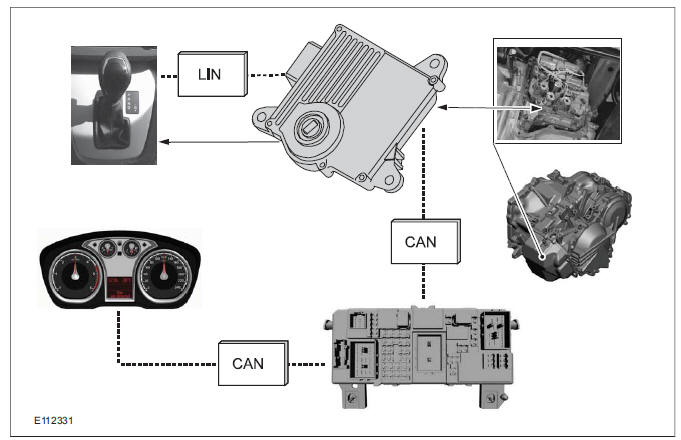
The following overview summarizes the input and output signals from the transmission control module.
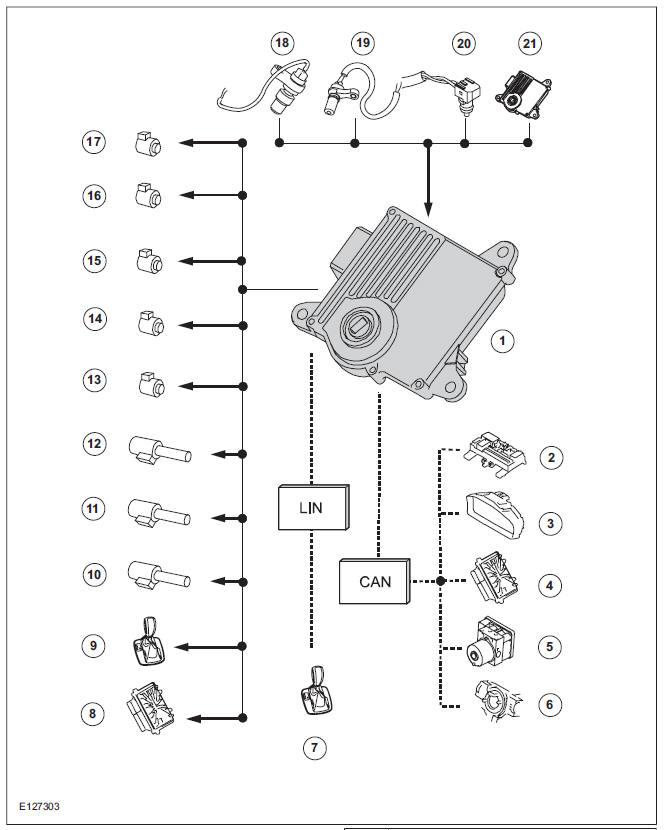
| Item | Description |
| 1 | TCM |
| 2 | GEM |
| 3 | Instrument Cluster |
| 4 | PCM |
| 5 | ABS |
| 6 | Cruise control |
| 7 | Select-shift switch module |
| 8 | PCM |
| 9 | Selector lever lock |
| 10 | PWMsolenoid valve - shift pressure (SLS) |
| 11 | PWMsolenoid valve for main line pressure (SLT) |
| 12 | PWM- solenoid valve - TCC (SLU) |
| 13 | Shift solenoid S1 (open when dormant) |
| 14 | Shift solenoid S2 (closed when dormant) |
| 15 | Shift solenoid S3 (closed when dormant) |
| 16 | Shift solenoid S4 (open when dormant) |
| 17 | Shift solenoid S5 (closed when dormant) |
| 18 | The TSS sensor |
| 19 | The OSS sensor |
| 20 | The TFT sensor |
| 21 | TR sensor in TCM |
Input signals
Hard wired
Item 18: ISS (input shaft speed) sensor
- Supplies information on the transmission input shaft speed. Used for calculations, for instance the shift process, checking the torque converter lockup and for diagnosis of the hydraulic/mechanical operations in the transmission.
Item 19: OSS sensor
- Supplies information on the transmission output shaft speed. Used for calculations, for instance the vehicle speed and for diagnosis of the hydraulic/mechanical operations in the transmission.
Item 20: TFT sensor
- Supplies information on the transmission fluid temperature. This information is used to adjust the shift times and the fluid pressure.
Item 21: TR sensor
- Supplies the TCM with the information on the chosen transmission range. Starting is only possible when the selector lever is in the P or N position. The sensor is a permanent magnet which creates a magnetic field over the different Hall sensors and in this way creates a specific voltage for each shift operation.
Via the LIN data bus
Item 7: Selector lever module (select-shift module)
- Indicates that the selector lever is locked in position P and supplies information on the sport mode status. Also transmits a control signal during select-shift gear changes and supplies information on the fault status in the selector lever module, so that the fault codes in the module can be stored as required.
Via the CAN data bus
Item 4: PCM
- Stop light switch ON/OFF, is used by the TCC.
- Coolant temperature, used for diagnosis of the transmission temperature sensor and for activating the catalytic converter.
- Engine speed >400 rpm = engine running.
Used for starting the transmission fluid pressure and diagnosis functions.
- Engine rpm. Used for checking the torque converter slip and the pressure build-up, which have an effect on the shift comfort.
- Kickdown. If the accelerator pedal is pressed down and the throttle plate is wide open, the PCM transmits a kickdown signal to the TCM.
- Current engine speed, used to check the line pressure of the transmission
- Throttle plate opening, used to calculate the gear changes. During sport mode and kickdown.
- Accelerator pedal position, used to calculate the shift threshold timings.
Item 5: ABS module
- Supplies information on the vehicle speed and also on the difference in speed between the left-hand and right-hand wheels. Prevents changing up if the speed difference is greater than 40 km/h, to protect the differential in the transmission.
Item 6: Vehicle speed control system
- Is used to calculate the acceleration, depending on the position of the resume and set buttons.
Output signals
Hard wired
Item 8: PCM
- Start inhibitor. Supplies the PCM with a signal that indicates whether the engine can be started or not.
Item 9: Selector lever module (select-shift module)
- Controls the solenoid switch in the selector lever unit.
Position 10: PWM solenoid valve - shift pressure (SLS)
- Matches the line pressure to a shift pressure and is activated for certain gears.
Position 11: PWM solenoid valve - main line pressure (SLT)
- Adjusts the linear line pressure for gear changes without jolts.
Position 12: PWM- solenoid valve - TCC (SLU)
- Matches the line pressure to a torque converter lock-up pressure. Is also used for certain gearshifts.
Items 13 - 17: Shift solenoids S1 - S5
- The TCM checks which gear is engaged as the solenoids become active in different patterns.
Via the LIN data bus
Item 7: Selector lever module (select-shift module)
- The TCM transmits a signal to the selector lever module which activates the LED (light emitting diode) in the selector mechanism assembly according to the selector lever position.
Via the CAN data bus
Item 2: GEM
- The selector lever module transmits a signal via the TCM, which indicates that the selector lever is locked in position P. The GEM uses this information to control the ignition switch key inhibit function.
- The TCM transmits a signal via the GEM to activate the back-up lamps.
Item 3: Instrument Cluster
- Current selector lever position. Used to indicate the selector lever position in the instrument cluster
- Check the warning lamps via the GEM. In the event of a fault, the general warning lamp lights.
- Text messages in the instrument cluster via the GEM. The driver receives various malfunction messages from the TCM.
- The TCM transmits signals on the CAN data bus to the PCM so that the MIL lights up in the event of emissions-related faults.
Item 4: PCM
- Transmission fluid temperature, used to compensate for increased loads at low fluid temperatures.
- Gear selected, used by the engine so that it can compensate for different loads.
- Torque converter lockup, used by the engine so that it can compensate for different loads.
- Next gear planned by the TCM, used by the engine to compensate for different loads.
- Requirement for a reduced engine torque during gear shifts, the engine reduces the engine torque during gear shifts.
- Torque limiting requirement, the engine limits the engine torque according to the gear engaged.
Item 5: ABS module
- Current gear, used to transmit a signal, not for shift control.
- Vehicle speed, used as reserve.
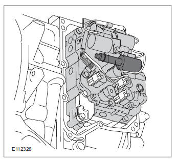
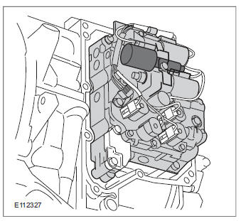
Control valve assembly
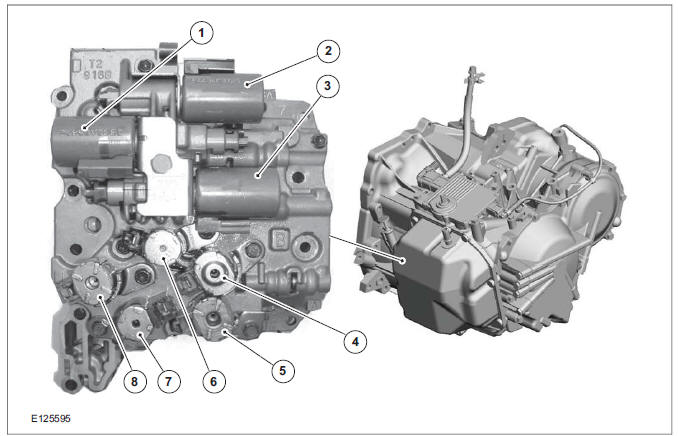
| Item | Description |
| 1 | PWMsolenoid valve for main line pressure (SLT) |
| 2 | PWM- solenoid valve - TCC (SLU) |
| 3 | PWMsolenoid valve - shift pressure (SLS) |
| 4 | Shift solenoid S4 |
| 5 | Shift solenoid S3 |
| 6 | Shift solenoid S1 |
| 7 | Shift solenoid S5 |
| 8 | Shift solenoid S2 |
The hydraulic pressure is distributed to the individual clutches and brakes in the valve body.
The hydraulic paths and the hydraulic pressure are controlled electronically via three PWM solenoid valves and five shift solenoid valves.
The shift solenoid valves S1-S5 are either in the 'open' or 'closed' state.
The control valves (SLT and SLS) regulate the hydraulic pressure in accordance with the duty cycle of the electrical PWM signal. The controlled hydraulic pressure enables smooth shifting or the generation of a defined slip through actuation of the relevant clutches and brakes.
The control valve (SLU) regulates the hydraulic pressure in accordance with the duty cycle of the electrical PWM signal. It controls the torque converter clutch. The PWM control achieves smooth engagement of the gears.
The shift timing is calculated by the TCM using the accelerator pedal position and vehicle speed.
Under normal conditions, the gears are shifted and the torque converter lockup is activated at low engines speeds in order to reduce the fuel consumption.
If the accelerator pedal is pressed down quickly, the TCM switches automatically into kickdown mode.
Function of the shift solenoid valves in the gears and when shifting gears
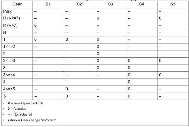
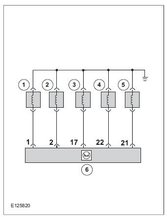
Shift solenoids S1 - S5
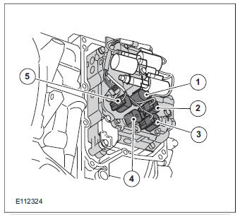
| Item | Description |
| 1 | Shift solenoid S1 |
| 2 | Shift solenoid S4 |
| 3 | Shift solenoid S3 |
| 4 | Shift solenoid S5 |
| 5 | Shift solenoid S2 |
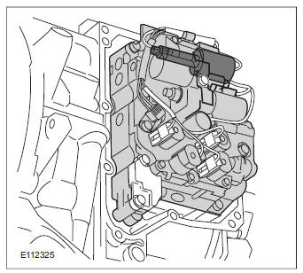
Shift solenoids S1, S2, S3, S4 and S5 are located in the control valve assembly on the front of the transmission.
Function
The shift solenoid valves are actuated by the TCM TCM. The shift solenoid valves S1 and S4 are fully open when de-energized. The shift solenoid valves S2, S3, and S5 are fully closed when de-energized.
They control gearshifting, while the TCM decides which gear should be engaged by activating the shift solenoid valves in different combinations.
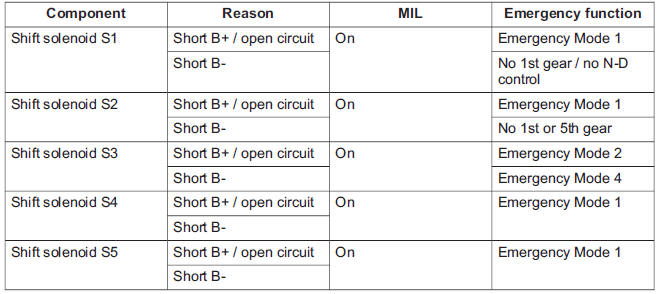
Consequences of signal failure
| Item | Description |
| 1 | Shift solenoid S1 |
| 2 | Shift solenoid S2 |
| 3 | Shift solenoid S3 |
| 4 | Shift solenoid S4 |
| 5 | Shift solenoid S5 |
| 6 | TCM connector 'C' |
If a shift solenoid valve fails, the MIL is activated and the vehicle can be driven in the appropriate emergency mode.
Failure of the shift solenoids
PWM- solenoid valve - TCC (SLU)
Installation position
The PWM solenoid valve for the TCC (SLU) is located in the valve body on the front of the transaxle.
Function
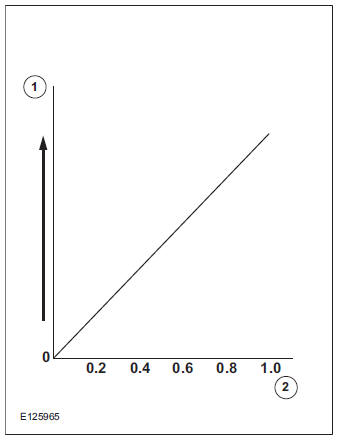
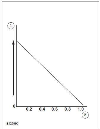
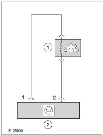
| Item | Description |
| 1 | Hydraulic pressure |
| 2 | Average current (A) |
The valve actuates the torque converter clutch as well as the reverse gear brake (B3) and 2nd - 5th gear brake (B2). The PWM control achieves smooth engagement of the gears. The two brakes are actuated in 1st and 2nd gear to guarantee engine braking.
The valve also actuates the torque converter in such a way that is works in three positions: 'open', 'controlled looping (slip lock-up mode)', and 'locked (full lock-up mode)'. The hydraulic function of the valve is linear.
In lockup mode the TCC is closed. The impeller and the turbine of the torque converter are friction locked. The engine torque acts directly on the transmission input shaft. Fuel consumption is reduced due to a reduction in the torque converter pump losses.
In slip lock-up mode, slip in the TCC is permitted in order to improve driving comfort. The hydraulic pressure acting on the TCM varies in accordance with the duty signal of the actuation signal generated by the PWM for the TCC solenoid valve for the TCC (SLU). The temperature of the transmission fluid increases in slip mode.
Consequences of signal failure
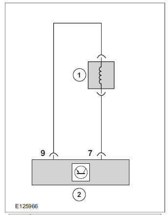
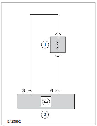
| Item | Description |
| 1 | PWM- solenoid valve - TCC (SLU) |
| 2 | TCM connector 'C' |
If the PWM solenoid valve for the TCC (SLU) fails, the MIL is activated and the vehicle can be driven in emergency mode 1.
PWM solenoid valve - shift pressure (SLS)
Installation position
The PWM solenoid valve for shift pressure (SLS) is located in the valve body on the front of the transaxle.
Function
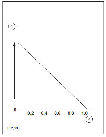
| Item | Description |
| 1 | Hydraulic pressure |
| 2 | Average current (A) |
The valve directly actuates the multi-plate brake (B1) in 2nd - 4th gear as well as the clutch (C2) in 5th and reverse gear. The PWM control achieves smooth engagement of the gears.
The hydraulic function of the valve is linear. The hydraulic valve is controlled by means of the varying current resulting from the current duty cycle. The system pressure is low with a high duty cycle, i.e. with high current intensity (approx. 1 A), and vice versa.
Consequences of signal failure
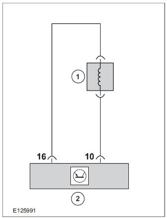
| Item | Description |
| 1 | PWMsolenoid valve - shift pressure (SLS) |
| 2 | TCM connector 'C' |
The shift pressure increases to the maximum value in the event of interruptions, which leads to hard gearshifts when shifting to another gear. The valve is then fully open.
If the PWM solenoid valve for shift pressure (SLS) fails, the MIL is activated and the vehicle can be driven in emergency mode 3.
PWM solenoid valve for main line pressure (SLT)
Installation position
The PWM solenoid valve - main line pressure (SLT) is located in the control valve assembly on the front of the transmission.
Function
| Item | Description |
| 1 | Hydraulic pressure |
| 2 | Average current (A) |
The PWM solenoid valve for main line pressure (SLT) is actuated proportionally by the TCM.
The TCM evaluates the accelerator pedal position and the current engine torque.
The main line pressure is adapted proportionally by the TCM via the PWM solenoid valve. This measure enables judder-free gearshifts.
The PWM solenoid valve is open when de-energized. In the case of faults and failure of the control system, the PWM solenoid valve remains fully open. The maximum main line pressure is applied.
Consequences of signal failure
| Item | Description |
| 1 | PWMsolenoid valve for main line pressure (SLT) |
| 2 | TCM connector 'C' |
The system pressure increases to the maximum value in the event of interruptions, which leads to hard gearshifts when shifting to another gear. The valve is then fully open.
If the PWM solenoid valve - main line pressure (SLT) fails, the MIL is activated and the vehicle can be driven in emergency mode 1.
Installation position
The TCC is an integral component of the torque converter.
Operation
The TCM controls the PWM via the TCC solenoid valve for the TCC (SLU). Based on the signals for engine speed and accelerator pedal position as well as vehicle speed, driving comfort is improved by linear actuation of the TCC.
Selector lever with integrated select-shift switch module
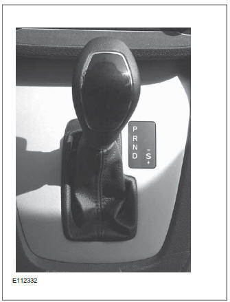
The selector lever unit is located in the central console. It is mechanically connected to the transmission by a selector cable which moves the gear selector shaft in the TR sensor.
The following components are integrated in the selector lever assembly:
- Select-shift switch module
- Selector lever lock solenoid.
- Switch contact for selector lever position 'P'
- LED for the selector lever position display
The selector lever has the following positions:
- P: Park position
- R: Reverse gear.
- N: Neutral position
- D: Automatically shift between all gears
- S: Sport and select-shift mode (manual gear changing)
If the selector lever is not in the 'P' position when the vehicle is exited, a signal is transmitted to the instrument cluster via the switch contact for selector lever position 'P'. When the driver door is opened, a message to move the selector lever to the 'P' position appears in the instrument cluster and the warning buzzer sounds. The vehicle cannot be electrically locked if the selector lever is not moved to the 'P' position.
Overview of the select-shift switch module
The select-shift switch module is located on the upper trim of the selector lever unit. The module is supplied with power by the TCM.
It uses the LIN databus to interact with the TCM, for instance to activate the selector lever position display.
It allows the automatic transmission gears to be changed up and down manually via the signals of the Hall sensors.
The select-shift switch module detects the selector lever position 'P' and 'S' via the integrated selector lever position sensors (Hall sensors).
A cable leading from the TCM passes directly to the select-shift switch module and is used to control the solenoid of the selector lever lock. The switching solenoid receives its voltage supply directly from the module.
In the event of a fault, a signal is transmitted to the TCM where all DTCs are stored.
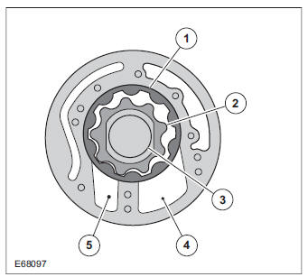
Oil pump
| Item | Description |
| 1 | Fluid pump rotor, outer |
| 2 | Fluid pump rotor, inner |
| 3 | Drive |
| 4 | Intake side |
| 5 | Delivery side |
The fluid pump operates on the principle of a G-rotor fluid pump.
The fluid pump draws transmission fluid from the fluid pan, builds up fluid pressure and then supplies it to the valve body.
The fluid pump is driven by the crankshaft via the torque converter housing.
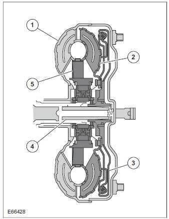
Torque converter with TCC
| Item | Description |
| 1 | Torque converter housing and impeller |
| 2 | Turbine |
| 3 | TCC |
| 4 | Transaxle input shaft |
| 5 | Stator with roller-type one-way clutch |
The torque converter transmits the output torque hydraulically from the engine to the transaxle input shaft.
The stator increases the torque up to the clutch take-up point. At the clutch take-up point, the speed difference between impeller and turbine is approximately 90 %.
In order to improve the efficiency, the torque converter features a hydraulically-activated TCC.
When the TCC is engaged, the torque is transmitted directly from the crankshaft via the torque converter housing to the transaxle input shaft.
Installation position
The TCC is an integral component of the torque converter.
Function
The TCM controls the PWM via the TCC solenoid valve for the TCC (SLU). Based on the signals for engine speed and accelerator pedal position as well as vehicle speed, driving comfort is improved by linear actuation of the TCC.
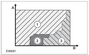
| Item | Description |
| A | APP (accelerator pedal position) |
| B | Vehicle speed |
| 1 | TCC disengaged |
| 2 | Slip lock-up mode |
| 3 | Full lock-up mode |
Full lock-up mode
In lockup mode the TCC is closed. The impeller and the turbine of the torque converter are friction locked. The engine torque acts directly on the transmission input shaft. Fuel consumption is reduced due to a reduction in the torque converter pump losses.
Full lock-up mode of the TCC is not generated at engine temperatures below 20 C (68 F).
Slip lock-up mode
In slip lock-up mode, slip in the TCC is permitted in order to improve driving comfort. The hydraulic pressure acting on the TCM varies in accordance with the duty signal of the actuation signal generated by the PWM for the TCC solenoid valve for the TCC (SLU). The automatic transaxle temperature increases in slip lock-up mode.
The TSS sensor
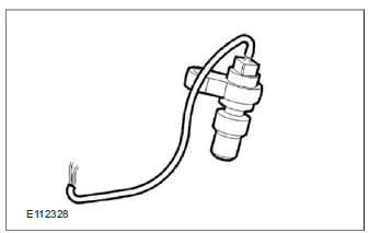
The TSS sensor is mounted at the top of the transmission housing. It is an active sensor and is supplied with 12 V.
Function
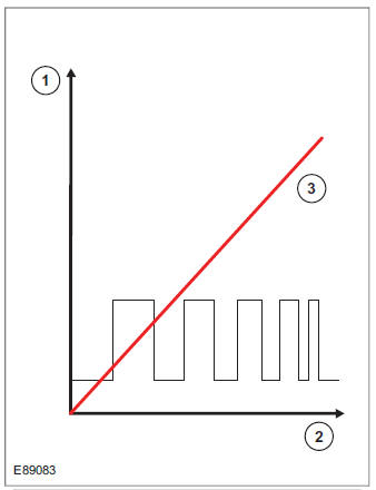
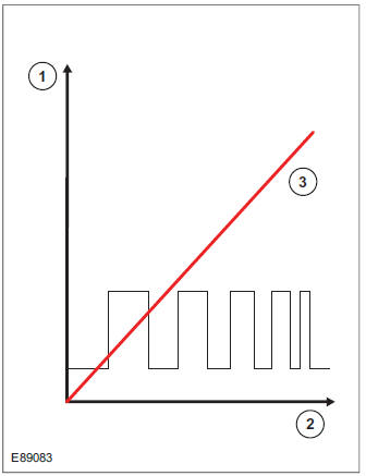
| Item | Description |
| 1 | Signal voltage |
| 2 | Signal frequency |
| 3 | Transmission input shaft speed |
The TSS sensor is a Hall sensor. It generates a square-wave signal, the frequency of which varies depending upon the speed of the transmission input shaft.
The frequency of the square-wave signal increases with the transmission input shaft speed. The TSS sensor picks up the speed at the housing of the 1st - 5th gear clutch (C1).
The TCM uses the information from the TSS sensor to determine the following parameters:
- Calculation of the torque reduction that needs to be requested by the PCM during shifting.
- Comparison of engine speed with transmission input shaft speed for calculation of torque converter slip.
- Calculation of the shift points.
- Calculation of the engaging and disengaging point for the TCC (lock-up function).
- Calculation of the current gear ratios by comparison of the OSS sensor signal.
Consequences of signal failure
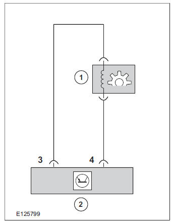
| Item | Description |
| 1 | The TSS sensor |
| 2 | TCM connector 'B' |
- Emergency mode 1
- Torque limitation is activated in order to protect the transaxle components from damage.
- The engine speed serves as a substitute value.
- When the engine is restarted (ignition switched off for approx. 15 seconds), the transaxle is no longer in limp home mode. There is no longer a fault indication on the instrument cluster, and the MIL is off. However, the fault remains stored in the TCM. If the fault is still present, limp home mode is reactivated.
The OSS sensor
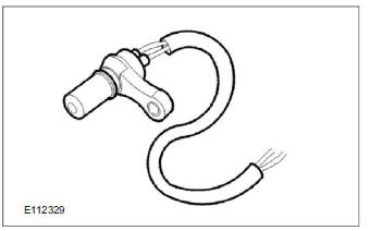
The OSS sensor is located at the rear of the transmission casing. It supplies signals about the transaxle output speed to the TCM.
Function
| Item | Description |
| 1 | Signal voltage |
| 2 | Signal frequency |
| 3 | Transmission input shaft speed |
The OSS sensor is a Hall sensor. The OSS sensor generates a square-wave signal, the frequency of which varies depending upon the speed of the transaxle output shaft. The frequency of the square-wave signal increases with the speed of the transmission output shaft.
The OSS sensor picks up the speed at the gear of the parking lock.
The TCM uses the information from the OSS sensor for the following parameters:
- Calculation of the degree of torque reduction that needs to be requested by the PCM during shifting.
- Calculation of the shift points.
- Calculation of the engaging and disengaging point for the TCC (lock-up function).
- Calculation of the current gear ratios by comparison of the TSS sensor signal.
Consequences of signal failure
| Item | Description |
| 1 | The OSS sensor |
| 2 | TCM connector 'B' |
- The torque converter lockup and adaptation functions are deactivated
- The wheel speed signal is transmitted by the ABS to the TCM via the HS-CAN data bus. This signal serves as a substitute value.
- When the engine is restarted (ignition switched off for approx. 15 seconds), the transaxle is no longer in limp home mode. There is no longer a fault indication on the instrument cluster, and the MIL is off. However, the fault remains stored in the TCM. If the fault is still present, limp home mode is reactivated.
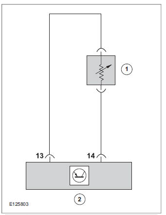
The TFT sensor
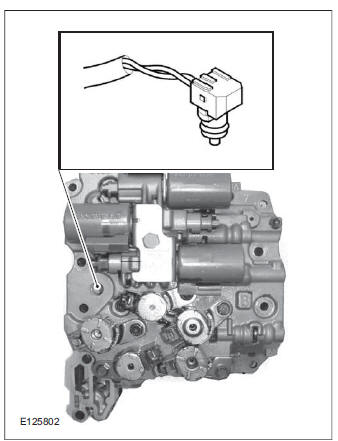
The TFT sensor is located in the valve body and is an integral component of the internal transaxle wiring harness.
Function
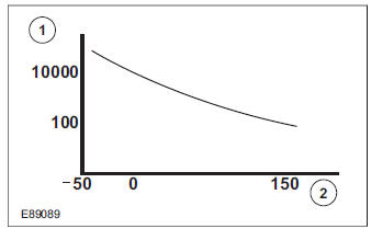
| Item | Description |
| 1 | Resistance (Ohms) |
| 2 | Temperature (C) |
The sensor is an NTC (negative temperature coefficient) (negative temperature coefficient) sensor. The voltage supply is 5 V. The transmission fluid temperature is detected by measuring the voltage drop across the NTC resistor.
The TCM uses the transmission fluid temperature information for the following calculations:
- Transaxle shift points
- If the transmission fluid temperatures are too high, slip lock-up of the TCC is prevented.
Consequences of signal failure
| Item | Description |
| 1 | The TFT sensor |
| 2 | TCM connector 'C' |
- No activation of TCC slip lock-up mode.
- No activation of TCC full lock-up mode.
- The MIL is activated.
- When the engine is restarted (ignition switched off for approx. 15 seconds), the transaxle is no longer in limp home mode. There is no longer a fault indication on the instrument cluster, and the MIL is off. However, the fault remains stored in the TCM. If the fault is still present, limp home mode is reactivated.
- If the sensor fails, a temperature substitute value of 30 C (86 F) is initially assumed. After 15 minutes driving, the substitute value is raised to 111 C.
The TR sensor
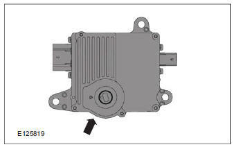
The TR sensor and the TCM form one unit. This unit is located at the top of the transmission casing, on the gear linkage.
Function
The TR sensor has three separate functions:
- Transmit a signal to the TCM about the selected transmission range.
- To transmit the signal to switch on the reversing lamps to the GEM when the selector lever is in the 'R' position.
- To transmit the start enable signal to the PCM when the selector lever is in the 'P' or 'N' position.
The TR sensor contains a permanent magnet and a linear Hall detector. It produces a signal voltage between 0 and 5 V. This signal voltage corresponds to the selector lever position currently chosen.
Voltage values for the different gears:
- P approximately 0.65 V
- R approximately 1.64 V
- N approximately 2.12 V
- D approximately 2.49 V
Consequences of signal failure
If the TR sensor fails, the MIL is activated and the vehicle can be driven in emergency mode 4. The vehicle can no longer be started for safety reasons after the ignition is switched off because the TCM does not detect the current transmission range.
If a shift solenoid valve fails, the MIL is activated and the vehicle can be driven in the appropriate emergency mode.
System Operation
Gearshift control
Power flow through the transmission
Service instructions
Component Description
Ford Kuga Service Manual
- General Information
- Jacking and Lifting
- Noise, Vibration and Harshness
- Suspension System - General Information
- Climate Control
- Auxiliary Climate Control
- Instrument Cluster and Panel Illumination
- Instrument Cluster
- Horn
- Warning Devices
- Parking Aid
- Charging System - General Information
- Battery, Mounting and Cables
- Generator and Regulator
- Voltage Converter/Inverter
- Information and Entertainment System - General Information
- Information and Entertainment System
- Exterior Lighting
- Interior Lighting
- Daytime Running Lamps (DRL)
- Module Communications Network
- Module Configuration
- Wiring Harnesses
- Anti-Theft - Active
- Anti-Theft - Passive
- Multifunction Electronic Modules
- Front End Body Panels
- Body Closures
- Interior Trim and Ornamentation
- Exterior Trim and Ornamentation
- Rear View Mirrors
- Seating
- Glass, Frames and Mechanisms
- Instrument Panel and Console
- Handles, Locks, Latches and Entry Systems
- Wipers and Washers
- Bumpers
- Safety Belt System
- Supplemental Restraint System
- Body Repairs - General Information
- Body Repairs - Vehicle Specific Information and Tolerance Checks
- Front End Sheet Metal Repairs
- Roof Sheet Metal Repairs
- Side Panel Sheet Metal Repairs
- Rear End Sheet Metal Repairs
- Paint - General Information
- Uni-Body, Subframe and Mounting System
- Suspension System - General Information
- Front Suspension
- Rear Suspension
- Wheels and Tires
- Driveshaft
- Rear Drive Axle/Differential
- Front Drive Halfshafts
- Rear Drive Halfshafts
- Brake System - General Information
- Front Disc Brake
- Rear Disc Brake
- Parking Brake and Actuation
- Hydraulic Brake Actuation
- Power Brake Actuation
- Anti-Lock Control
- Anti-Lock Control - Stability Assist
- Steering System - General Information
- Power Steering
- Steering Linkage
- Steering Column
- Steering Column Switches
- Engine System - General Information
- Engine- 2.5L Duratec (147kW/200PS) - VI5
- Engine Cooling
- Fuel Charging and Controls-2.5L Duratec (147kW/200PS) - VI5
- Fuel Charging and Controls - Turbocharger- 2.5L Duratec (147kW/200PS) - VI5
- Accessory Drive - 2.5L Duratec (147kW/200PS) - VI5
- Starting System- 2.5L Duratec (147kW/200PS) - VI5
- Engine Ignition - 2.5L Duratec (147kW/200PS) - VI5
- Engine Emission Control - 2.5L Duratec (147kW/200PS) - VI5
- Intake Air Distribution and Filtering - 2.5L Duratec (147kW/200PS) - VI5
- Evaporative Emissions
- Electronic Engine Controls
- Automatic Transmission/Transaxle
- Transmission/Transaxle Cooling
- Automatic Transmission/Transaxle External Controls
- Transfer Case
- Exhaust System-
- Fuel System
- Fuel Tank and Lines
- Acceleration Control
- Speed Control
- Climate Control System
- Climate Control
Main Categories

0.015