 Ford Kuga Service ManualAutomatic Transmission/Transaxle » Transmission Description (System Operation and Component Description)
System Operation
System Operation
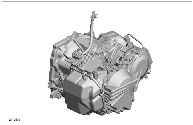
The AW55 5-gear automatic transaxle is a fully automatic, electronically controlled automatic transaxle. The fifth gear is an overdrive which saves fuel.
The maximum input torque is 330 Nm.
Gear changes are controlled by an electro-hydraulic system.
The gear ratios are achieved by means of a combined planetary gear set and a Simpson set.
Three multi-plate clutches, four multi-plate brakes and one band brake as well as two one-way clutches control the various ratios.
The clutches and brakes are hydraulically operated by electrically actuated solenoid valves. The valves are actuated by the TCM depending on the driving conditions and the driver's requirements.
The TCC is activated in gears 3, 4 and 5. The TCC is driven in interlock mode and in slip mode.
Defined slip achieves a smooth and therefore comfortable clutch engagement of the TCC.
Control of slip mode depends on the engine speed, accelerator pedal position and vehicle speed signals provided by the ECM (engine control module). This controls the rate of slip by comparing the engine speed and the turbine shaft speed.
The TSS sensor and the OSS sensor use the Hall effect principle. The TCM can regulate the slip in the torque converter by comparing the engine speed with the transmission speed.
All parameters for actuating the clutches and the TCC are determined by the TCM as a function of the operating parameters. The automatic transaxle features a self-learning strategy.
The fundamental parameters for gear shifting are the accelerator pedal position and the vehicle speed.
Gear selection can either be performed automatically or in select-shift mode. The selected transmission range or gear (in select-shift mode) is indicated to the driver in the instrument panel.
In selector lever position "S", the driver can manually select the gears (select-shift mode). Up (+) and down (-) shifts are made by moving the selector lever in the appropriate direction.
Hydraulic limp home modes maintain limited operation in the event of failure of important electrical components.
Under normal conditions, the transmission fluid is filled for the service life of the transaxle and does not need to be changed.
A dipstick is used to check the fluid level in the transmission.
Functionality overview
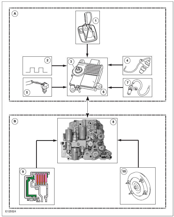
| Item | Description |
| A | Electronic Control System |
| B | Hydraulic Control System |
| 1 | Select-shift switch module |
| 2 | CAN (controller area network) bus input signals |
| 3 | The TR sensor |
| 4 | The TSS sensor |
| 5 | The TFT sensor |
| 6 | TCM |
| 7 | OSS (output shaft speed) sensor |
| 8 | Solenoid valves in valve body |
| 9 | Clutches and brakes |
| 10 | TCC |
The function is divided into an electronic and a hydraulic control system.
Electronic Control System
Depending on the input signals, the TCM mounted on the transmission actuates the solenoid valves in the valve body. The TCM calculates and stores adaptive data, fault codes and values for diagnosis.
The TR sensor is integrated in the TCM.
Hydraulic Control System
When the engine is running, a fluid pump integrated in the transaxle housing generates the hydraulic pressure required for controlling the automatic transaxle.
Through actuation of the solenoid valves, hydraulic pressure is applied to the clutches and brakes via hydraulic channels in the valve body and the transaxle. The control valves regulate the hydraulic pressure in accordance with the duty cycle of the electrical PWM signal. The controlled hydraulic pressure enables smooth shifting or the generation of a defined slip through actuation of the relevant clutches and brakes.
Solenoid valves are either in the 'open' or 'closed' state.
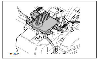
Type plate
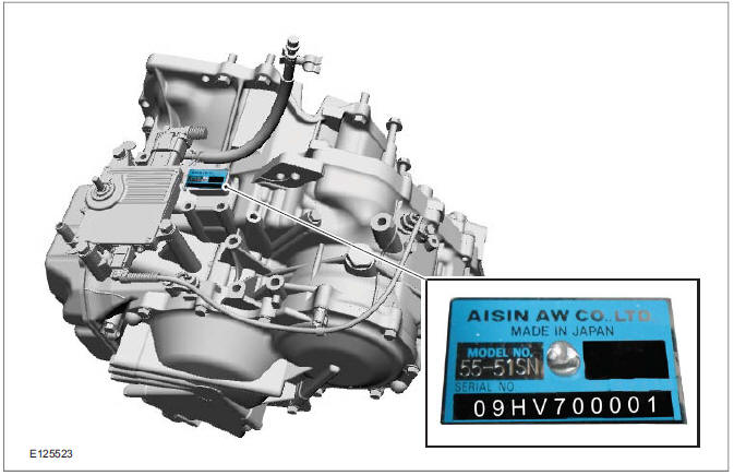
The transaxle identification is located on the rear/top of the transaxle housing in the direction of travel.
Serial number of the transmission
Example: 09HV70001
- 09: year of manufacture, 2009
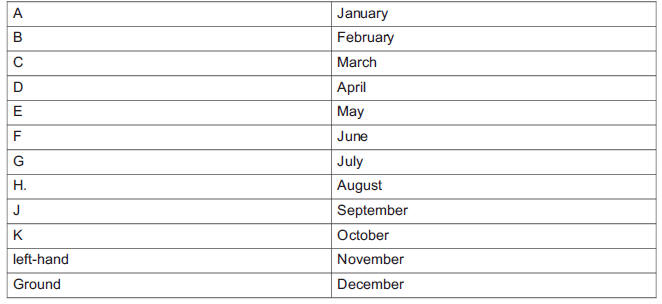
- H: code letter for the month of manufacture, August
- V7: automatic transaxle type 55-51SN
- 00001: Production number for the specified month
Identification letter coding
Markings on the TCM
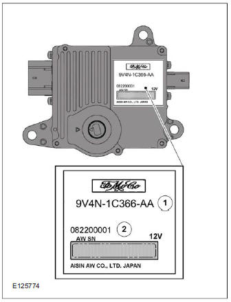
The name plate is located on the TCM.
Serial number of the TCM
Example: 082200001
- 08: year of manufacture, 2008
- 22: code for the calendar week
- 00001: Production number for the specified calendar week
Transmission Control
Depending on the input signals, the TCM mounted on the transmission actuates the solenoid valves in the valve body. The TCM calculates and stores adaptive data, fault codes and values for diagnosis.
The TR sensor is integrated in the TCM.
The TCM adapts the gear changing to ensure that the correct gear is selected for the style of driving, the engine load, driver requirements, vehicle speed etc. This leads to lower fuel consumption together with improved comfort through smoother gear changes and lower noise levels.
The TCM receives information on the driver's desired transmission range and type of driving mode. In contrast to a transmission which is only controlled hydraulically, the control module can calculate the best times to shift gear and activate torque converter lockup by using the signals from the sensors in the transmission and the engine management system.
The control module enables small changes in the operating conditions to be made and adapts the various transmission functions to ensure that the correct gear is always selected in relation to the type of driving mode.
The TCM has adaptive capabilities. This ensures smooth gear changes throughout the whole service life of the transmission.
To exactly determine the activation points of the gear shifts and torque converter lockup on the basis of the type of driving mode chosen, the TCM receives the following information:
- Transmission range chosen (TR sensor).
- Type of driving mode chosen (normal/sport/select-shift).
- Transmission input shaft speed (TSS sensor).
- Transmission output shaft speed (OSS sensor).
- Transmission fluid temperature (TFT sensor).
- The engine speed and the torque as well as the throttle plate opening - from the PCM via the CAN data bus.
- Actuation of the accelerator pedal - from the PCM via the CAN data bus.
- Coolant temperature - from the PCM via the CAN data bus.
- Vehicle speed - from the ABS via the CAN data bus.
- Actuation of the brake pedal - from the ABS via the CAN data bus.
Pin assignment for TCM connector 'A' (connection to vehicle)
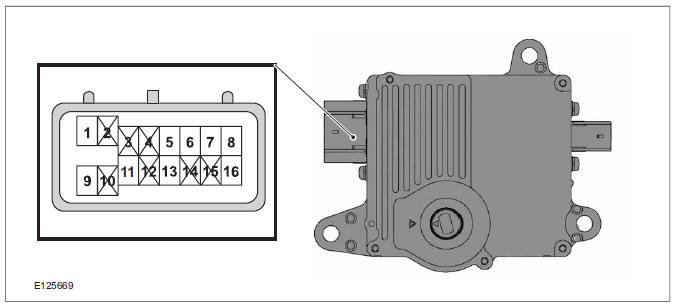
| Item | Description |
| 1 | Battery (+) |
| 2 | not assigned |
| 3 | not assigned |
| 4 | not assigned |
| 5 | Starter motor inhibitor signal to the PCM |
| 6 | CAN (low) |
| 7 | LIN (local interconnect network) |
| 8 | CAN (high) |
| 9 | GND (ground) |
| 10 | not assigned |
| 11 | Battery (+) via ignition switch |
| 12 | not assigned |
| 13 | Selector lever lock |
| 14 | not assigned |
| 15 | not assigned |
| 16 | Voltage supply for select-shift switch module |
Pin assignment for TCM connector 'B' (connection to transaxle)
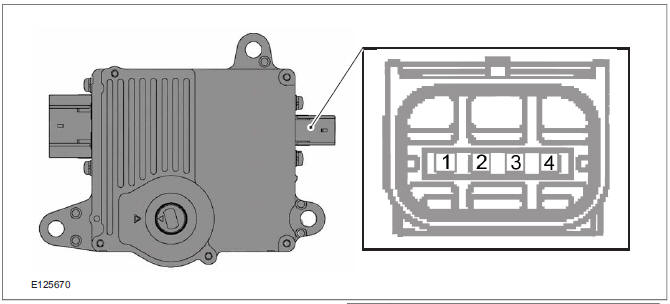
| Item | Description |
| 1 | OSS(-) |
| 2 | OSS(+) |
| 3 | TSS(+) |
| 4 | TSS(-) |
Pin assignment for TCM connector 'C' (connection to transaxle)
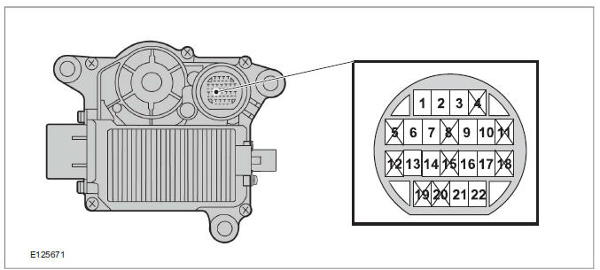
| Item | Description |
| 1 | Shift solenoid valve S1 (+) |
| 2 | Shift solenoid valve (S2) (+) |
| 3 | PWM solenoid valve - main line pressure (SLT) (+) |
| 4 | not assigned |
| 5 | not assigned |
| 6 | PWM solenoid valve - main pressure line (SLT) (-) |
| 7 | PWM solendoid valve - TCC (SLU) (-) |
| 8 | not assigned |
| 9 | PWM solenoid valve - TCC (SLU) (+) |
| 10 | PWMsolenoid valve - shift pressure (SLS) (-) |
| 11 | not assigned |
| 12 | not assigned |
| 13 | TFT sensor (-) |
| 14 | TFT sensor (+) |
| 15 | not assigned |
| 16 | PWMsolenoid valve - shift pressure (SLS) (+) |
| 17 | Shift solenoid valve (S3) (+) |
| 18 | not assigned |
| 19 | not assigned |
| 20 | not assigned |
| 21 | Shift solenoid valve (S5) (+) |
| 22 | Shift solenoid valve (S4) (+) |
Operation
Depending on the input signals, the TCM mounted on the transmission actuates the solenoid valves in the valve body. The TCM calculates and stores adaptive data, fault codes and values for diagnosis.
The TCM adapts the gear changing to ensure that the correct gear is selected for the style of driving, the engine load, driver requirements, vehicle speed etc. This leads to lower fuel consumption together with improved comfort through smoother gear changes and lower noise levels.
The TCM receives information on the driver's desired transmission range and type of driving mode. In contrast to a transmission which is only controlled hydraulically, the control module can calculate the best times to shift gear and activate torque converter lockup by using the signals from the sensors in the transmission and the engine management system.
The control module enables small changes in the operating conditions to be made and adapts the various transmission functions to ensure that the correct gear is always selected in relation to the type of driving mode.
The TCM has adaptive capabilities. This ensures smooth gear changes throughout the whole service life of the transmission.
To exactly determine the activation points of the gear shifts and torque converter lockup on the basis of the type of driving mode chosen, the TCM receives the following information:
- Selected transmission range (TR sensor)
- Selected driving mode (normal/sport/select-shift)
- Transmission input shaft speed (TSS sensor)
- Transmission output shaft speed (OSS sensor)
- Transmission fluid temperature (TFT sensor)
- The engine speed and the torque as well as the throttle plate opening - from the PCM via the CAN databus
- Actuation of accelerator - from the PCM via the CAN databus
- The coolant temperature - from the PCM via the CAN databus
- Road speed - from the ABS module via the CAN databus
- Actuation of brake pedal - from the PCM via the CAN databus
System Operation
Gearshift control
Power flow through the transmission
Service instructions
Component Description
Ford Kuga Service Manual
- General Information
- Jacking and Lifting
- Noise, Vibration and Harshness
- Suspension System - General Information
- Climate Control
- Auxiliary Climate Control
- Instrument Cluster and Panel Illumination
- Instrument Cluster
- Horn
- Warning Devices
- Parking Aid
- Charging System - General Information
- Battery, Mounting and Cables
- Generator and Regulator
- Voltage Converter/Inverter
- Information and Entertainment System - General Information
- Information and Entertainment System
- Exterior Lighting
- Interior Lighting
- Daytime Running Lamps (DRL)
- Module Communications Network
- Module Configuration
- Wiring Harnesses
- Anti-Theft - Active
- Anti-Theft - Passive
- Multifunction Electronic Modules
- Front End Body Panels
- Body Closures
- Interior Trim and Ornamentation
- Exterior Trim and Ornamentation
- Rear View Mirrors
- Seating
- Glass, Frames and Mechanisms
- Instrument Panel and Console
- Handles, Locks, Latches and Entry Systems
- Wipers and Washers
- Bumpers
- Safety Belt System
- Supplemental Restraint System
- Body Repairs - General Information
- Body Repairs - Vehicle Specific Information and Tolerance Checks
- Front End Sheet Metal Repairs
- Roof Sheet Metal Repairs
- Side Panel Sheet Metal Repairs
- Rear End Sheet Metal Repairs
- Paint - General Information
- Uni-Body, Subframe and Mounting System
- Suspension System - General Information
- Front Suspension
- Rear Suspension
- Wheels and Tires
- Driveshaft
- Rear Drive Axle/Differential
- Front Drive Halfshafts
- Rear Drive Halfshafts
- Brake System - General Information
- Front Disc Brake
- Rear Disc Brake
- Parking Brake and Actuation
- Hydraulic Brake Actuation
- Power Brake Actuation
- Anti-Lock Control
- Anti-Lock Control - Stability Assist
- Steering System - General Information
- Power Steering
- Steering Linkage
- Steering Column
- Steering Column Switches
- Engine System - General Information
- Engine- 2.5L Duratec (147kW/200PS) - VI5
- Engine Cooling
- Fuel Charging and Controls-2.5L Duratec (147kW/200PS) - VI5
- Fuel Charging and Controls - Turbocharger- 2.5L Duratec (147kW/200PS) - VI5
- Accessory Drive - 2.5L Duratec (147kW/200PS) - VI5
- Starting System- 2.5L Duratec (147kW/200PS) - VI5
- Engine Ignition - 2.5L Duratec (147kW/200PS) - VI5
- Engine Emission Control - 2.5L Duratec (147kW/200PS) - VI5
- Intake Air Distribution and Filtering - 2.5L Duratec (147kW/200PS) - VI5
- Evaporative Emissions
- Electronic Engine Controls
- Automatic Transmission/Transaxle
- Transmission/Transaxle Cooling
- Automatic Transmission/Transaxle External Controls
- Transfer Case
- Exhaust System-
- Fuel System
- Fuel Tank and Lines
- Acceleration Control
- Speed Control
- Climate Control System
- Climate Control
Main Categories

0.0146