 Ford Kuga Service ManualEngine- 2.5L Duratec (147kW/200PS) - VI5 » Engine (Overview)
Cylinder head
Cylinder head
The cylinder head consists of two parts. The top half of the cylinder head consists of a valve cover with integral camshaft bearing caps.
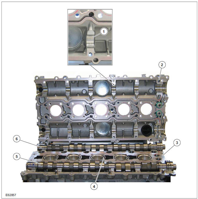
| Item | Description |
| 1 | Camshaft bearings |
| 2 | Valve cover |
| 3 | Cylinder head |
| 4 | Spark plug well sealing ring |
| 5 | Exhaust camshaft |
| 6 | intake camshaft |
A conventional cylinder head gasket is installed between the cylinder head and the cylinder block.
The gaskets between the other mating faces are fluid gaskets.
Camshafts
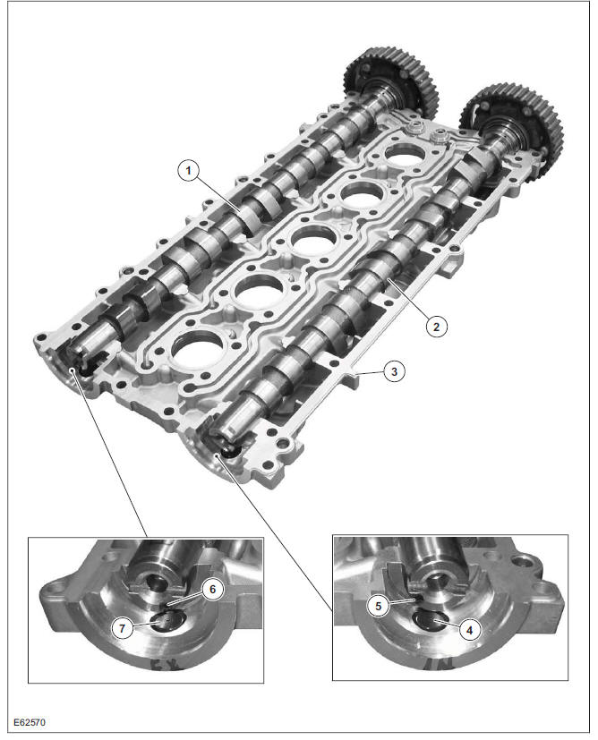
| Item | Description |
| 1 | Exhaust camshaft |
| 2 | intake camshaft |
| 3 | Valve cover |
| 4 | CMP Sensor - intake camshaft |
| 5 | Intake camshaft reference mark |
| 6 | Exhaust camshaft reference mark |
| 7 | CMP Sensor - exhaust camshaft |
CAUTION: Before removal, mark the camshafts as the intake and exhaust camshafts can be mixed up.
A reference mark for the CMP sensor is machined into each camshaft. When the camshafts are set precisely to the timing marks, the machined mark on the exhaust camshaft is located roughly at the 5 o'clock position and the machined mark on the intake camshaft is located at 8 o'clock.
When changing the toothed belts it is not necessary to dismantle the camshaft adjustment units. A special tool prevents the VCT control units from turning during the adjustment process by locking the two VCT control units to one another.
A further special tool is needed to fix the camshafts in the adjustment position. The special tool engages in corresponding recesses for the reference marks on the CMP sensors.
Each camshaft is fixed in place using four bearing caps and the bearing cap VVT. The bearing caps must not be changed around and must always be fitted in their original positions.
The VCT control units for the intake and exhaust camshafts are moved into the locked base position when the engine is stopped through the engagement of a spring-loaded locking pin. The movement to the locked base position is assisted by the tensile force of the timing belt for the intake VCT control unit. With the exhaust VCT control unit, a spring inside the control unit additionally assists in reaching the locked base position. The intake VCT control unit is in the "retarded timing" position and the exhaust VCT control unit is in the "advanced timing" position when in the locked base position. The lock is hydraulically released when the engine is started depending on the oil pressure.
The mechanical valve tappets are maintenance free.
Timing marks
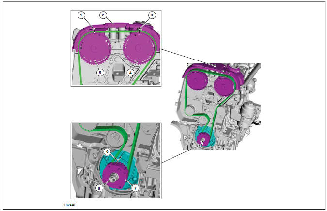
| Item | Description |
| 1 | Exhaust camshaft pulley timing mark |
| 2 | Engine front cover with timing marks |
| 3 | Intake camshaft pulley timing mark |
| 4 | Intake camshaft drive gear |
| 5 | Exhaust camshaft drive gear |
| 6 | Crankshaft timing belt pulley timing mark |
| 7 | Crankshaft timing belt pulley |
| 8 | Crankshaft |
The front engine cover must always be fitted when checking and adjusting the valve timing or timing belt tension, as the timing marks for both camshaft pulleys are provided on its front end.
Correct timing belt tension is ensured by the automatic timing belt tensioner.
No direction of movement is specified when using a new timing belt. If, however, the old timing belt is reused, the direction of movement must be marked prior to removal.
Once the timing belt has been correctly tensioned, the engine must be rotated by hand two turns clockwise at the crankshaft in order to allow a subsequent check of the timing belt tension and adjustment.
General
Cylinder head
Cylinder block
Ford Kuga Service Manual
- General Information
- Jacking and Lifting
- Noise, Vibration and Harshness
- Suspension System - General Information
- Climate Control
- Auxiliary Climate Control
- Instrument Cluster and Panel Illumination
- Instrument Cluster
- Horn
- Warning Devices
- Parking Aid
- Charging System - General Information
- Battery, Mounting and Cables
- Generator and Regulator
- Voltage Converter/Inverter
- Information and Entertainment System - General Information
- Information and Entertainment System
- Exterior Lighting
- Interior Lighting
- Daytime Running Lamps (DRL)
- Module Communications Network
- Module Configuration
- Wiring Harnesses
- Anti-Theft - Active
- Anti-Theft - Passive
- Multifunction Electronic Modules
- Front End Body Panels
- Body Closures
- Interior Trim and Ornamentation
- Exterior Trim and Ornamentation
- Rear View Mirrors
- Seating
- Glass, Frames and Mechanisms
- Instrument Panel and Console
- Handles, Locks, Latches and Entry Systems
- Wipers and Washers
- Bumpers
- Safety Belt System
- Supplemental Restraint System
- Body Repairs - General Information
- Body Repairs - Vehicle Specific Information and Tolerance Checks
- Front End Sheet Metal Repairs
- Roof Sheet Metal Repairs
- Side Panel Sheet Metal Repairs
- Rear End Sheet Metal Repairs
- Paint - General Information
- Uni-Body, Subframe and Mounting System
- Suspension System - General Information
- Front Suspension
- Rear Suspension
- Wheels and Tires
- Driveshaft
- Rear Drive Axle/Differential
- Front Drive Halfshafts
- Rear Drive Halfshafts
- Brake System - General Information
- Front Disc Brake
- Rear Disc Brake
- Parking Brake and Actuation
- Hydraulic Brake Actuation
- Power Brake Actuation
- Anti-Lock Control
- Anti-Lock Control - Stability Assist
- Steering System - General Information
- Power Steering
- Steering Linkage
- Steering Column
- Steering Column Switches
- Engine System - General Information
- Engine- 2.5L Duratec (147kW/200PS) - VI5
- Engine Cooling
- Fuel Charging and Controls-2.5L Duratec (147kW/200PS) - VI5
- Fuel Charging and Controls - Turbocharger- 2.5L Duratec (147kW/200PS) - VI5
- Accessory Drive - 2.5L Duratec (147kW/200PS) - VI5
- Starting System- 2.5L Duratec (147kW/200PS) - VI5
- Engine Ignition - 2.5L Duratec (147kW/200PS) - VI5
- Engine Emission Control - 2.5L Duratec (147kW/200PS) - VI5
- Intake Air Distribution and Filtering - 2.5L Duratec (147kW/200PS) - VI5
- Evaporative Emissions
- Electronic Engine Controls
- Automatic Transmission/Transaxle
- Transmission/Transaxle Cooling
- Automatic Transmission/Transaxle External Controls
- Transfer Case
- Exhaust System-
- Fuel System
- Fuel Tank and Lines
- Acceleration Control
- Speed Control
- Climate Control System
- Climate Control
Main Categories

0.0163