 Ford Kuga Service ManualGeneral Information
Symbols Glossary
Symbols Glossary
Symbols are used inside the graphics and in the text area to enhance the information display.
Movement Symbols
Movement symbols provide detailed information to a required component movement. These component movements can be rotational or 1-3 dimensional movements.
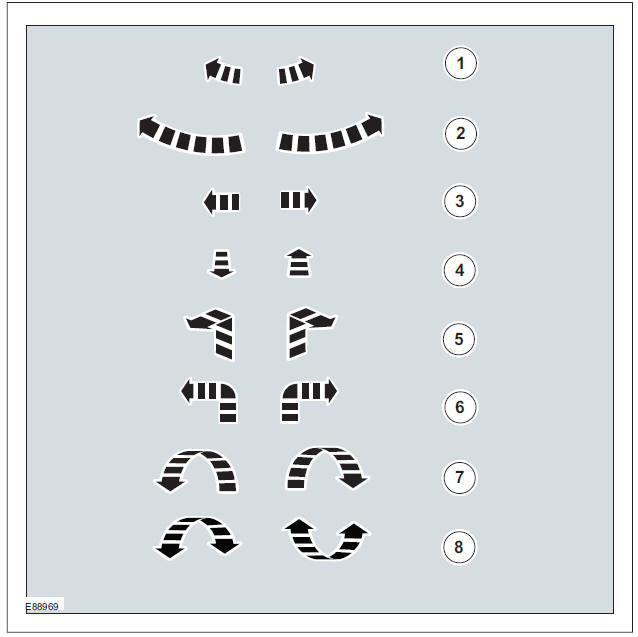
| Item | Description |
| 1 | Minor component movement clockwise/counterclockwise |
| 2 | Major component movement clockwise/counterclockwise |
| 3 | Component movement to the left/right/up/down |
| 4 | Component movement towards/away |
| 5 | 3 dimensional component movement |
| 6 | 2 dimensional component movement |
| 7 | 3 dimensional component rotation |
| 8 | 3 dimensional component cycling |
Turn Symbols
Turn symbols are used to provide further information on the direction or angle of component turns.
| Item | Description |
| 1 | Set the selector lever to the park (P) position |
| 2 | Set the selector lever to the reverse ( R ) position |
| 3 | Set the selector lever to the neutral (N) position |
| 4 | Set the selector lever to the drive (D) position |
| 5 | Set the selector lever with manual shift pattern to the park (D) position |
| 6 | Set the selector lever with manual shift pattern to the manual (M) position |
| 7 | Set the selector lever with manual shift pattern to the shift down (-) position |
| 8 | Set the selector lever with manual shift pattern to the shift up (+) position |
| 9 | Set the gearshift lever to the neutral (N) position |
| 10 | Further gearshift lever positions that may appear in illustrations |
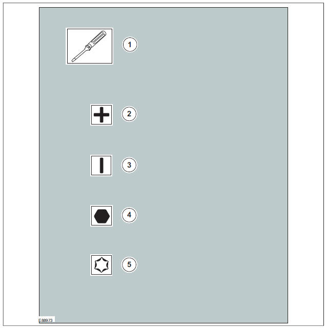
Screwdriver symbols
The screwdriver symbols are used to show which screwdriver bit is recommended to carry out a procedure step.
| Item | Description |
| 1 | Turn the component clockwise through 45 |
| 2 | Turn the component counterclockwise through 45 |
| 3 | Turn the component clockwise through 90 |
| 4 | Turn the component counterclockwise through 90 |
| 5 | Turn the component clockwise through 180 |
| 6 | Turn the component counterclockwise through 180 |
| 7 | Turn the component clockwise through 2 complete turns |
| 8 | Turn the component counterclockwise through 2 complete turns |
Steering Wheel Symbols
Steering wheel symbols are used to provide further information to a required steering wheel position or steering column lock status.
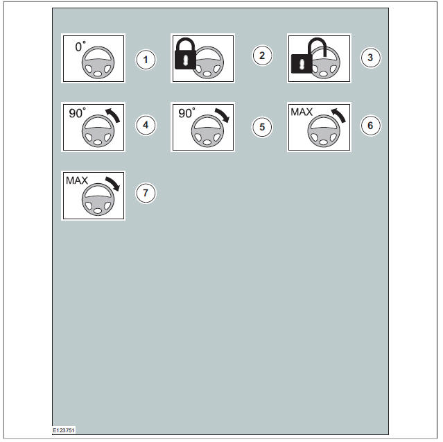
| Item | Description |
| 1 | Screwdriver |
| 2 | Cross bladed screwdriver |
| 3 | Flat bladed screwdriver |
| 4 | Hexagonal screwdriver |
| 5 | TORX screwdriver |
Pliers symbols
The pliers symbols are used to show which pliers is recommended to carry out a procedure step.
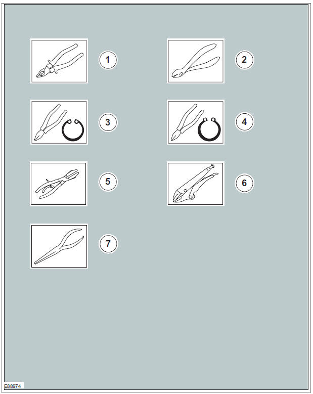
| Item | Description |
| 1 | Combination pliers |
| 2 | Side cutter pliers |
| 3 | Securing ring pliers - inner |
| 4 | Securing ring pliers - outer |
| 5 | Hose clamp pliers |
| 6 | Locking pliers |
| 7 | Long nose pliers |
Drill symbols
The drill symbols are used to show which type and size of drill bit is recommended to carry out a procedure step.
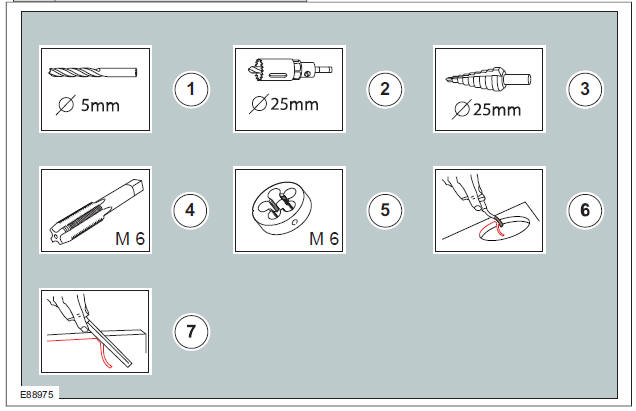
| Item | Description |
| 1 | Drill bit with a specified diameter |
| 2 | Hole saw with a specified diameter |
| 3 | Stepped drill bit with a specified diameter |
| 4 | Tap with a specified diameter |
| 5 | Die with a specified diameter |
| 6 | Scraper for circular holes |
| 7 | Scraper for straight edges |
Cutting tool symbols
The cutting tool symbols are used to show which type of cutting tool is recommended to carry out a procedure step.
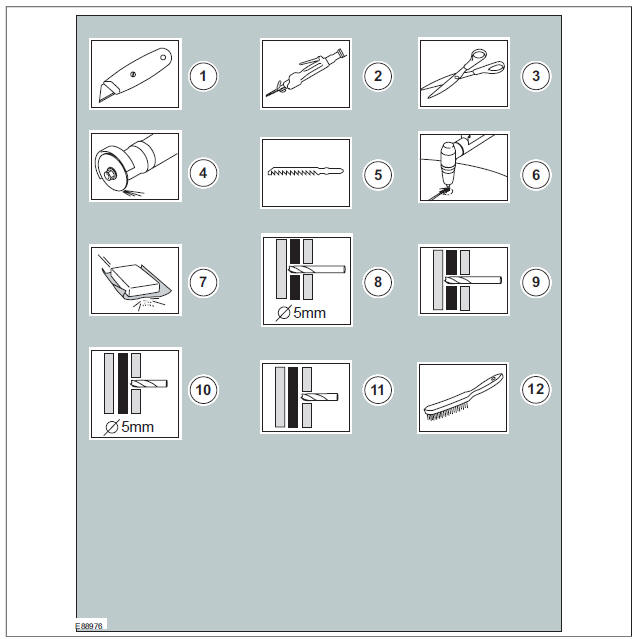
| Item | Description |
| 1 | Cutting knife |
| 2 | Air body saw |
| 3 | Scissors |
| 4 | Grinder |
| 5 | Jig saw |
| 6 | Plasma cutter |
| 7 | Sanding Paper |
| 8 | Drill through the shown number of body panel layers with a specified diameter |
| 9 | Drill through the shown number of body panel layers with a suitable diameter |
| 10 | Drill through 1 body panel layer with a specified diameter |
| 11 | Drill through 1 body panel layer with a suitable diameter |
| 12 | Wire brush |
Apply Chemical or load symbols
The apply chemical or load symbols are used to show where to apply which type of chemical or load to carry out a procedure step.
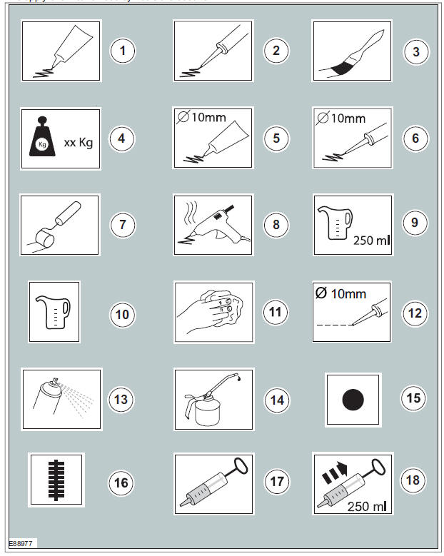
| Item | Description |
| 1 | Apply the substance from the specified tube |
| 2 | Apply the substance from the specified cartridge |
| 3 | Apply the specified chemical with a brush |
| 4 | Apply the specified load to the specified component |
| 5 | Apply a bead with a specific diameter from the specified tube |
| 6 | Apply a bead with a specific diameter from the specified cartridge |
| 7 | Apply the specified chemical with a roller |
| 8 | Apply hot glue to the specified component |
| 9 | Apply the specified amount of fluid from the fluid can |
| 10 | Apply fluid from the fluid can |
| 11 | Clean the specified component with the specified material |
| 12 | Apply a broken bead from the specified tube |
| 13 | Apply the specified chemical from a spray can |
| 14 | Apply the specified lubricant to the specified component |
| 15 | Apply spot welds to the specified component |
| 16 | Apply a continuous weld to the specified component |
| 17 | Handle the fluid using a syringe |
| 18 | Extract the specified amount of fluid using a syringe |
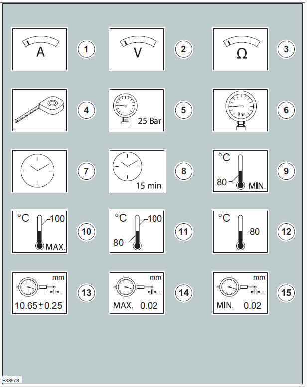
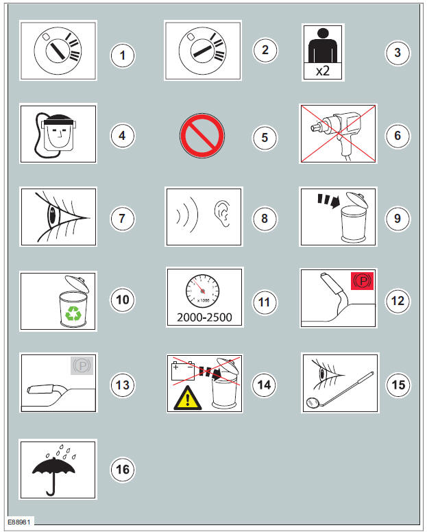
Measurement symbols
The measurement symbols are used to show where to measure which type of measurement to carry out a procedure step.
| Item | Description |
| 4 | Self contained breathing apparatus |
| 5 | General prohibition used in combination with another symbol |
| 6 | Do not use power tools |
| 7 | Visual check |
| 8 | Noise check |
| 9 | Dispose the specified component |
| 10 | Replaced by item 9 (Dispose the specified component) |
| 11 | Set the engine speed to the specified value |
| 12 | Fully apply the parking brake lever |
| 13 | Fully release the parking brake lever |
| 14 | Do not dispose of batteries into the waste bin |
| 15 | Visual check using a mirror |
| 16 | Area/component must be dry |
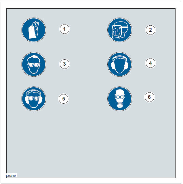
Mandatory Protective equipment - Health and safety symbols
The protective equipment symbols advise to use a mandatory protective equipment to avoid or at least reduce possible health and safety risks.
| Item | Description |
| 1 | Measure the current using a digital multimeter |
| 2 | Measure the voltage using a digital multimeter |
| 3 | Measure the resistance using a digital multimeter |
| 4 | Measure the length/distance |
| 5 | Check that the specified pressure is available using a suitable pressure gauge |
| 6 | Measure the pressure at the specified port using a suitable pressure gauge |
| 7 | Measure the time using a suitable stopwatch |
| 8 | Wait for the specified period of time |
| 9 | The specified task requires the specified minimum temperature |
| 10 | The specified task requires the specified maximum temperature not to be exceeded |
| 11 | The specified task requires the specified temperature range |
| 12 | The specified task requires the specified temperature |
| 13 | Measure and check for the specified value using a dial indicator gauge |
| 14 | Measure and check for the specified MAX value using a dial indicator gauge |
| 15 | Measure and check for the specified MIN value using a dial indicator gauge |
General equipment symbols
The general equipment symbols are used to show where to use which type of general equipment to carry out a procedure step.
| Item | Description |
| 1 | Wear protective gloves |
| 2 | Wear face guard |
| 3 | Wear safety goggles |
| 4 | Wear ear protectors |
| 5 | Wear safety goggles and ear protectors |
| 6 | Wear a respirator |
Prohibition - Health and safety symbols and component damage
The prohibition symbols are used to prohibit the specified actions to avoid or at least reduce possible component damage and health and safety risks.
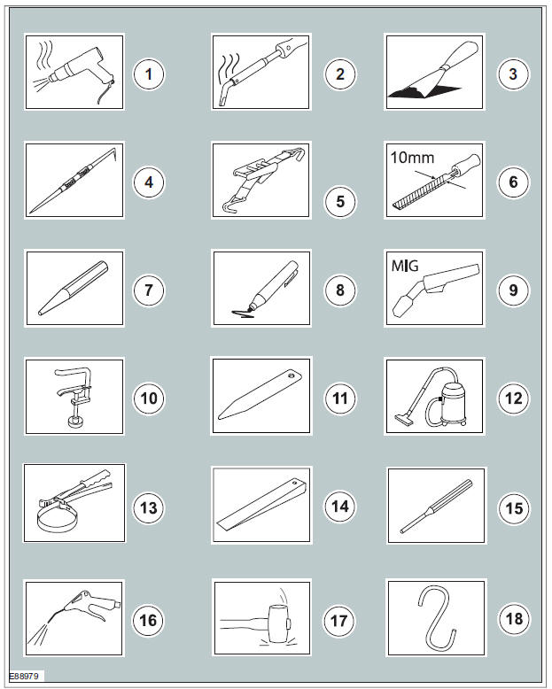
| Item | Description |
| 1 | Hot air gun |
| 2 | Soldering iron |
| 3 | Scraper |
| 4 | Scriber |
| 5 | Securing strap |
| 6 | File with a specified size |
| 7 | Center punch |
| 8 | Marker |
| 9 | Metal inert gas (MIG) welding equipment |
| 10 | Hose clamp |
| 11 | Interior trim remover |
| 12 | Vacuum cleaner |
| 13 | Strap wrench |
| 14 | Wedge |
| 15 | Pin Punch |
| 16 | Air blow gun |
| 17 | Mallet |
| 18 | Relocate and support the component |
Material symbols
The material symbols are used to show where to use which type of material to carry out a procedure step.
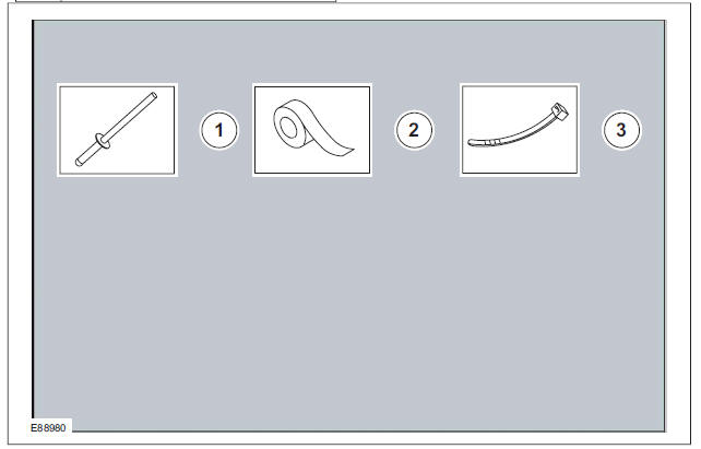
| Item | Description |
| 1 | Remove/Install the specified blind rivet |
| 2 | Apply tape to the specified component/area |
| 3 | Remove/Install the specified cable tie |
Miscellaneous symbols
These symbols provide further information that is required to carry out a procedure step.
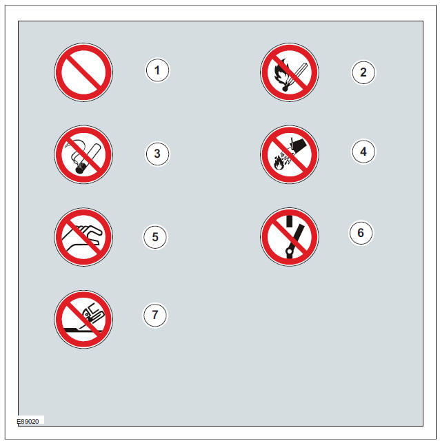
| Item | Description |
| 1 | General prohibition symbol |
| 2 | No naked flames |
| 3 | No smoking |
| 4 | No water |
| 5 | Do not touch |
| 6 | Do not switch |
| 7 | No grinding |
Warning symbols - Health and safety and component damage
The warning symbols are used to advise on hazardous conditions to avoid or at least reduce possible component damage and health and safety risks.
| Item | Description |
| 1 | Set the ignition switch to the 0 position |
| 2 | Set the ignition switch to the II position |
| 3 | The procedure step requires the aid of the specified number of supporting technicians |
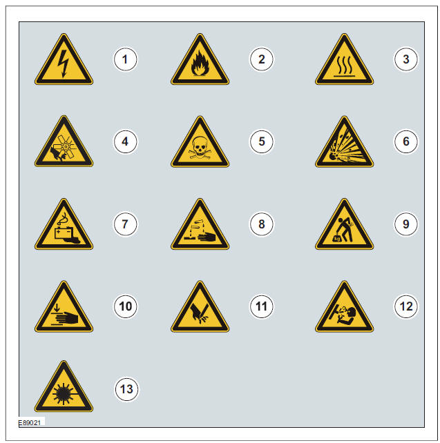
| Item | Description |
| 1 | Hazardous voltage/Electrical shock/Electrocution |
| 2 | Fire Hazard/Highly flammable |
| 3 | Burn hazard/Hot surface |
| 4 | Automatic start-up |
| 5 | Toxic |
| 6 | Explosive material |
| 7 | Battery hazard |
| 8 | Corrosive material |
| 9 | Lifting hazard |
| 10 | Hand crush/Force from above |
| 11 | Cutting of fingers or hand |
| 12 | Pressure hazard |
| 13 | Invisible laser radiation. Do not view directly with optical instruments (magnifiers). Class 1M laser product |
Control Diagram symbols - Description and Operation procedures
These symbols provide further information on the type of connectivity, direction of flow or type of data bus of a system.
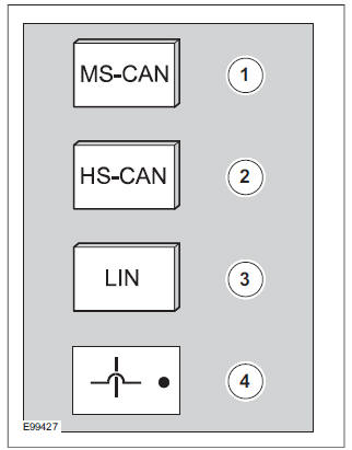
| Item | Description |
| 1 | Mid-speed Controller Area Network (CAN) |
| 2 | High-speed Controller Area Network (CAN) |
| 3 | Local Interconnect Network (LIN) |
| 4 | Wires crossing not connected |
About This Manual
Symbols Glossary
Steering System Health and Safety Precautions
Health and Safety Precautions
Standard Workshop Practices
Solvents, Sealants and Adhesives
Road/Roller Testing
Air Conditioning (A/C) System Health and Safety Precautions
Battery and Battery Charging Health and Safety Precautions
Brake System Health and Safety Precautions
Engine Cooling System Health and Safety Precautions
Window Glass Health and Safety Precautions
Petrol and Petrol-Ethanol Fuel Systems Health and Safety Precautions
Supplemental Restraint System (SRS) Health and Safety Precautions
Body Repair Health and Safety and General Precautions
Ford Kuga Service Manual
- General Information
- Jacking and Lifting
- Noise, Vibration and Harshness
- Suspension System - General Information
- Climate Control
- Auxiliary Climate Control
- Instrument Cluster and Panel Illumination
- Instrument Cluster
- Horn
- Warning Devices
- Parking Aid
- Charging System - General Information
- Battery, Mounting and Cables
- Generator and Regulator
- Voltage Converter/Inverter
- Information and Entertainment System - General Information
- Information and Entertainment System
- Exterior Lighting
- Interior Lighting
- Daytime Running Lamps (DRL)
- Module Communications Network
- Module Configuration
- Wiring Harnesses
- Anti-Theft - Active
- Anti-Theft - Passive
- Multifunction Electronic Modules
- Front End Body Panels
- Body Closures
- Interior Trim and Ornamentation
- Exterior Trim and Ornamentation
- Rear View Mirrors
- Seating
- Glass, Frames and Mechanisms
- Instrument Panel and Console
- Handles, Locks, Latches and Entry Systems
- Wipers and Washers
- Bumpers
- Safety Belt System
- Supplemental Restraint System
- Body Repairs - General Information
- Body Repairs - Vehicle Specific Information and Tolerance Checks
- Front End Sheet Metal Repairs
- Roof Sheet Metal Repairs
- Side Panel Sheet Metal Repairs
- Rear End Sheet Metal Repairs
- Paint - General Information
- Uni-Body, Subframe and Mounting System
- Suspension System - General Information
- Front Suspension
- Rear Suspension
- Wheels and Tires
- Driveshaft
- Rear Drive Axle/Differential
- Front Drive Halfshafts
- Rear Drive Halfshafts
- Brake System - General Information
- Front Disc Brake
- Rear Disc Brake
- Parking Brake and Actuation
- Hydraulic Brake Actuation
- Power Brake Actuation
- Anti-Lock Control
- Anti-Lock Control - Stability Assist
- Steering System - General Information
- Power Steering
- Steering Linkage
- Steering Column
- Steering Column Switches
- Engine System - General Information
- Engine- 2.5L Duratec (147kW/200PS) - VI5
- Engine Cooling
- Fuel Charging and Controls-2.5L Duratec (147kW/200PS) - VI5
- Fuel Charging and Controls - Turbocharger- 2.5L Duratec (147kW/200PS) - VI5
- Accessory Drive - 2.5L Duratec (147kW/200PS) - VI5
- Starting System- 2.5L Duratec (147kW/200PS) - VI5
- Engine Ignition - 2.5L Duratec (147kW/200PS) - VI5
- Engine Emission Control - 2.5L Duratec (147kW/200PS) - VI5
- Intake Air Distribution and Filtering - 2.5L Duratec (147kW/200PS) - VI5
- Evaporative Emissions
- Electronic Engine Controls
- Automatic Transmission/Transaxle
- Transmission/Transaxle Cooling
- Automatic Transmission/Transaxle External Controls
- Transfer Case
- Exhaust System-
- Fuel System
- Fuel Tank and Lines
- Acceleration Control
- Speed Control
- Climate Control System
- Climate Control
Main Categories

0.0148