 Ford Kuga Service ManualInformation and Entertainment System - General Information » Cellular Phone
Pinpoint Tests
Pinpoint Tests
NOTE: ENTER the following PIN number on the cellular phone to configure the cellular phone to the PSE module: 0000.
NOTE: Use a digital multimeter for all electrical measurements.
PINPOINT TEST A : NO COMMUNICATION WITH THE PORTABLE SUPPORT ELECTRONICS (PSE) MODULE
| TEST CONDITIONS | DETAILS/RESULTS/ACTIONS |
| A1: CHECK FOR VOLTAGE AT THE PSE MODULE | |
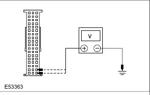 |
Yes GO to A2. No REPAIR circuit 29-MC12C (OG/YE) or circuit 29-MC12B (OG/YE) as necessary. TEST the system for normal operation. |
| A2: CHECK THE PSE MODULE GROUND CIRCUIT(S) | |
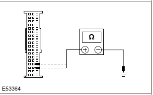 |
Yes INSTALL a new PSE module. TEST the system for normal operation. No REPAIR circuit 91-MC12 (BK/YE) or circuit 91-MC12A (BK/YE) as necessary. TEST the system for normal operation. |
| PINPOINT TEST B : THE CELLULAR PHONE MICROPHONE IS NOT OPERATING CORRECTLY | |
| B1: CHECK THAT THE VOICE IS BEING TRANSMITTED DURING A TELEPHONE CONVERSION OUTSIDE OF THE VEHICLE | |
| NOTE: Make sure that the Bluetooth functionality is disabled for this test. | |
Yes GO to B2. No REFER to the cellular phone Owner's Guide. |
|
| B2: CHECK CIRCUIT 8-MC8 (WH/RD) FOR OPEN | |
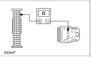 |
Yes GO to B3. No REPAIR the circuit. TEST the system for normal operation. |
| B3: CHECK CIRCUIT 3-MC8 (BK) FOR OPEN | |
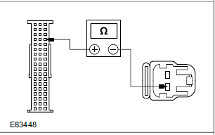 |
Yes INSTALL a new microphone. TEST the system for normal operation. No REPAIR the circuit. TEST the system for normal operation. If the concern persists, INSTALL a new PSE module. TEST the system for normal operation. |
| PINPOINT TEST C : THE MUTE SYMBOL IS DISPLAYED ON THE AUDIO UNIT WHEN TRYING TO OPERATE THE CELLULAR PHONE SYSTEM | |
| C1: CONFIGURE THE PSE MODULE TO THE VEHICLE | |
Yes Carry out the PSE module configuration procedure again. If the concern persists, INSTALL a new PSE module. TEST the system for normal operation. No TEST the system for normal operation. |
|
Principles of Operation
Inspection and Verification
Diagnostic Trouble Code (DTC) Index Chart
Symptom Chart
Pinpoint Tests
Ford Kuga Service Manual
- General Information
- Jacking and Lifting
- Noise, Vibration and Harshness
- Suspension System - General Information
- Climate Control
- Auxiliary Climate Control
- Instrument Cluster and Panel Illumination
- Instrument Cluster
- Horn
- Warning Devices
- Parking Aid
- Charging System - General Information
- Battery, Mounting and Cables
- Generator and Regulator
- Voltage Converter/Inverter
- Information and Entertainment System - General Information
- Information and Entertainment System
- Exterior Lighting
- Interior Lighting
- Daytime Running Lamps (DRL)
- Module Communications Network
- Module Configuration
- Wiring Harnesses
- Anti-Theft - Active
- Anti-Theft - Passive
- Multifunction Electronic Modules
- Front End Body Panels
- Body Closures
- Interior Trim and Ornamentation
- Exterior Trim and Ornamentation
- Rear View Mirrors
- Seating
- Glass, Frames and Mechanisms
- Instrument Panel and Console
- Handles, Locks, Latches and Entry Systems
- Wipers and Washers
- Bumpers
- Safety Belt System
- Supplemental Restraint System
- Body Repairs - General Information
- Body Repairs - Vehicle Specific Information and Tolerance Checks
- Front End Sheet Metal Repairs
- Roof Sheet Metal Repairs
- Side Panel Sheet Metal Repairs
- Rear End Sheet Metal Repairs
- Paint - General Information
- Uni-Body, Subframe and Mounting System
- Suspension System - General Information
- Front Suspension
- Rear Suspension
- Wheels and Tires
- Driveshaft
- Rear Drive Axle/Differential
- Front Drive Halfshafts
- Rear Drive Halfshafts
- Brake System - General Information
- Front Disc Brake
- Rear Disc Brake
- Parking Brake and Actuation
- Hydraulic Brake Actuation
- Power Brake Actuation
- Anti-Lock Control
- Anti-Lock Control - Stability Assist
- Steering System - General Information
- Power Steering
- Steering Linkage
- Steering Column
- Steering Column Switches
- Engine System - General Information
- Engine- 2.5L Duratec (147kW/200PS) - VI5
- Engine Cooling
- Fuel Charging and Controls-2.5L Duratec (147kW/200PS) - VI5
- Fuel Charging and Controls - Turbocharger- 2.5L Duratec (147kW/200PS) - VI5
- Accessory Drive - 2.5L Duratec (147kW/200PS) - VI5
- Starting System- 2.5L Duratec (147kW/200PS) - VI5
- Engine Ignition - 2.5L Duratec (147kW/200PS) - VI5
- Engine Emission Control - 2.5L Duratec (147kW/200PS) - VI5
- Intake Air Distribution and Filtering - 2.5L Duratec (147kW/200PS) - VI5
- Evaporative Emissions
- Electronic Engine Controls
- Automatic Transmission/Transaxle
- Transmission/Transaxle Cooling
- Automatic Transmission/Transaxle External Controls
- Transfer Case
- Exhaust System-
- Fuel System
- Fuel Tank and Lines
- Acceleration Control
- Speed Control
- Climate Control System
- Climate Control
Main Categories

0.0144