 Ford Kuga Service ManualAutomatic Transmission/Transaxle » Transmission Description (Overview)
Components of the electronic control
Components of the electronic control
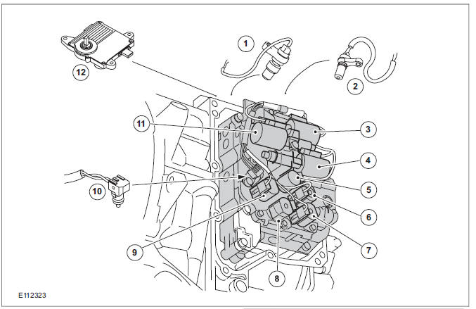
| Item | Description |
| 1 | The TSS sensor |
| 2 | The OSS sensor |
| 3 | PWM (pulse width modulation)- solenoid valve - TCC (torque converter clutch) (SLU) |
| 4 | PWMsolenoid valve - shift pressure (SLS) |
| 5 | Shift solenoid S1 |
| 6 | Shift solenoid S4 |
| 7 | Shift solenoid S3 |
| 8 | Shift solenoid S5 |
| 9 | Shift solenoid S2 |
| 10 | The TFT (transmission fluid temperature) sensor |
| 11 | PWMsolenoid valve for main line pressure (SLT) |
| 12 | TCM with integrated TR sensor |
Depending on the input signals, the TCM mounted on the transaxle actuates the solenoid valves S1-S5 in the valve body. The solenoid valves are either in the "open" or "closed" state.
The (SLT and SLS) control valves regulate the hydraulic pressure according to the pulse/pause ratio of the electrical PWM signal. The controlled hydraulic pressure enables smooth shifting or the generation of a defined slip through actuation of the relevant clutches and brakes.
The shift timing is calculated by the TCM using the accelerator pedal position and vehicle speed.
Under normal conditions, gear shifting and torque converter lockup occur at low engine speeds to reduce fuel consumption.
If the accelerator pedal is pressed down quickly, the TCM switches automatically into kickdown mode.
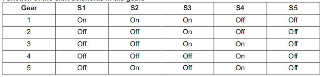
Function of the shift solenoids in the gears
Overview of the brakes, clutches and one-way clutches
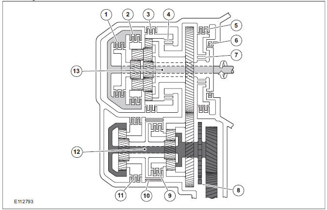
| Item | Description |
| 1 | Clutch C2: Connects the input shaft with the sun gear. |
| 2 | Clutch C1: Connects the input shaft with the rear gear. |
| 3 | Brake B3: Locks the annulus of the front planetary gear. |
| 4 | One-way clutch F2: Locks the front annulus in the counterclockwise direction. |
| 5 | Brake B2: Prevents the sun gear on the input shaft from turning counterclockwise |
| 6 | Brake B1: Locks the sun gear on the input shaft. |
| 7 | One-way clutch F1: Prevents the sun gear on the input shaft turning counterclockwise when B2 is activated. |
| 8 | Park System |
| 9 | Clutch C3: Connects the sun gear with the front planetary gear carrier on the output shaft. |
| 10 | Brake band B4: Blocks the the sun gear on the output shaft. |
| 11 | Brake B5: Locks the rear planetary gear carrier on the output shaft. |
| 12 | Output shaft - transaxle |
| 13 | Input shaft - transaxle |
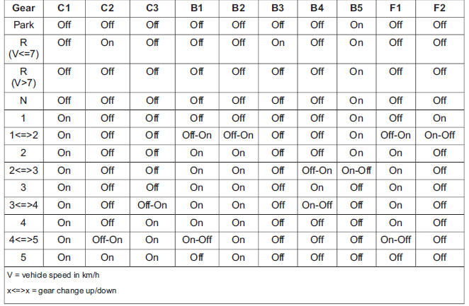
Function of the clutches and brakes in the gears and during gear changes
TCM
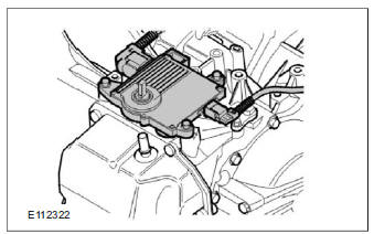
The TCM with integral TR sensor is mounted on the transaxle casing.
Input and output signals at the TCM
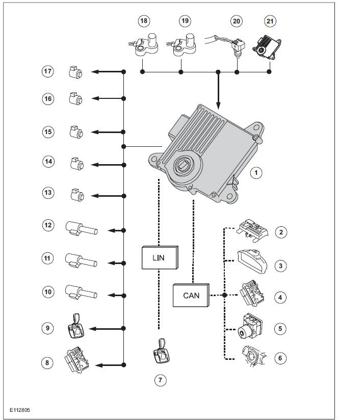
| Item | Description |
| 1 | TCM |
| 2 | GEM (generic electronic module) |
| 3 | Instrument Cluster |
| 4 | PCM (powertrain control module) |
| 5 | ABS (anti-lock brake system) |
| 6 | Speed control |
| 7 | Select-shift switch module |
| 8 | PCM |
| 9 | Selector lever lock |
| 10 | PWMsolenoid valve - shift pressure (SLS) |
| 11 | PWMsolenoid valve for main line pressure (SLT) |
| 12 | PWM- solenoid valve - TCC (SLU) |
| 13 | Shift solenoid S1 (open when dormant) |
| 14 | Shift solenoid S2 (closed when dormant) |
| 15 | Shift solenoid S3 (closed when dormant) |
| 16 | Shift solenoid S4 (open when dormant) |
| 17 | Shift solenoid S5 (closed when dormant) |
| 18 | The TSS sensor |
| 19 | The OSS sensor |
| 20 | The TFT sensor |
| 21 | TR sensor in TCM |
Components of the AW55 automatic transaxle
Transaxle cooling
External shift mechanism
Components of the electronic control
Knowing and Understanding Customer Concerns
Testing Possible Causes of Transmission Control Faults
Visual inspection
Towing the vehicle
Push-starting the Vehicle
Selector Lever Emergency Release
Transmission Fluid Level Check
Changing the Transmission Fluid
Diagnosis with IDS
Programming the 'N' position of the TR sensor
Resetting the values learned by the TCM
Ford Kuga Service Manual
- General Information
- Jacking and Lifting
- Noise, Vibration and Harshness
- Suspension System - General Information
- Climate Control
- Auxiliary Climate Control
- Instrument Cluster and Panel Illumination
- Instrument Cluster
- Horn
- Warning Devices
- Parking Aid
- Charging System - General Information
- Battery, Mounting and Cables
- Generator and Regulator
- Voltage Converter/Inverter
- Information and Entertainment System - General Information
- Information and Entertainment System
- Exterior Lighting
- Interior Lighting
- Daytime Running Lamps (DRL)
- Module Communications Network
- Module Configuration
- Wiring Harnesses
- Anti-Theft - Active
- Anti-Theft - Passive
- Multifunction Electronic Modules
- Front End Body Panels
- Body Closures
- Interior Trim and Ornamentation
- Exterior Trim and Ornamentation
- Rear View Mirrors
- Seating
- Glass, Frames and Mechanisms
- Instrument Panel and Console
- Handles, Locks, Latches and Entry Systems
- Wipers and Washers
- Bumpers
- Safety Belt System
- Supplemental Restraint System
- Body Repairs - General Information
- Body Repairs - Vehicle Specific Information and Tolerance Checks
- Front End Sheet Metal Repairs
- Roof Sheet Metal Repairs
- Side Panel Sheet Metal Repairs
- Rear End Sheet Metal Repairs
- Paint - General Information
- Uni-Body, Subframe and Mounting System
- Suspension System - General Information
- Front Suspension
- Rear Suspension
- Wheels and Tires
- Driveshaft
- Rear Drive Axle/Differential
- Front Drive Halfshafts
- Rear Drive Halfshafts
- Brake System - General Information
- Front Disc Brake
- Rear Disc Brake
- Parking Brake and Actuation
- Hydraulic Brake Actuation
- Power Brake Actuation
- Anti-Lock Control
- Anti-Lock Control - Stability Assist
- Steering System - General Information
- Power Steering
- Steering Linkage
- Steering Column
- Steering Column Switches
- Engine System - General Information
- Engine- 2.5L Duratec (147kW/200PS) - VI5
- Engine Cooling
- Fuel Charging and Controls-2.5L Duratec (147kW/200PS) - VI5
- Fuel Charging and Controls - Turbocharger- 2.5L Duratec (147kW/200PS) - VI5
- Accessory Drive - 2.5L Duratec (147kW/200PS) - VI5
- Starting System- 2.5L Duratec (147kW/200PS) - VI5
- Engine Ignition - 2.5L Duratec (147kW/200PS) - VI5
- Engine Emission Control - 2.5L Duratec (147kW/200PS) - VI5
- Intake Air Distribution and Filtering - 2.5L Duratec (147kW/200PS) - VI5
- Evaporative Emissions
- Electronic Engine Controls
- Automatic Transmission/Transaxle
- Transmission/Transaxle Cooling
- Automatic Transmission/Transaxle External Controls
- Transfer Case
- Exhaust System-
- Fuel System
- Fuel Tank and Lines
- Acceleration Control
- Speed Control
- Climate Control System
- Climate Control
Main Categories

0.0145